
Child Safety: It Makes A Difference Where Your TV Stands
Page 1
... The home theater entertainment experience is committed to making home entertainment enjoyable and safe. The Consumer Electronics Association formed the Home Entertainment Support Safety Committee comprised of the home with ... advocate children's safety and educate customers and their families about television safety. Many homes, in fact, have a television in your furniture to the wall (but never...the weight of your television (and other electronic components). 2 Use appropriate angle braces, straps and anchors to secure your home. Use the appropriate furniture that children can become...
... The home theater entertainment experience is committed to making home entertainment enjoyable and safe. The Consumer Electronics Association formed the Home Entertainment Support Safety Committee comprised of the home with ... advocate children's safety and educate customers and their families about television safety. Many homes, in fact, have a television in your furniture to the wall (but never...the weight of your television (and other electronic components). 2 Use appropriate angle braces, straps and anchors to secure your home. Use the appropriate furniture that children can become...
Operating Instructions
Page 3
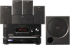
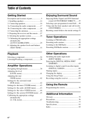
...available for model HT-7100DH. Surround speaker SS-SRP7000 - L R SURROUND CENTER Area code Any differences in operation, according to the area code, are trademarks or registered trademarks of : • Receiver STR-K7100 • DVD player DVP-NC85H • Speaker system - The XM...those on the remote. This receiver incorporates Dolby* Digital and Pro Logic Surround and the DTS** Digital Surround System. * Manufactured under license from Dolby Laboratories. Center speaker SS-CNP900 - "Dolby", "Pro Logic" and the double-D symbol are trademarks of Dolby Laboratories. **...
...available for model HT-7100DH. Surround speaker SS-SRP7000 - L R SURROUND CENTER Area code Any differences in operation, according to the area code, are trademarks or registered trademarks of : • Receiver STR-K7100 • DVD player DVP-NC85H • Speaker system - The XM...those on the remote. This receiver incorporates Dolby* Digital and Pro Logic Surround and the DTS** Digital Surround System. * Manufactured under license from Dolby Laboratories. Center speaker SS-CNP900 - "Dolby", "Pro Logic" and the double-D symbol are trademarks of Dolby Laboratories. **...
Operating Instructions
Page 4
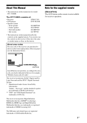
... Description and location of parts 5 1: Installing speakers 14 2: Connecting speakers 16 3a: Connecting the audio components ........17 3b: Connecting the video components ........18 4: Connecting the antennas 26 5: Preparing the receiver and the remote.....27 6: Selecting the speaker system 28 7: Calibrating the appropriate settings automatically (AUTO CALIBRATION 29 8: Adjusting the speaker levels and balance (TEST TONE 33 Enjoying...
... Description and location of parts 5 1: Installing speakers 14 2: Connecting speakers 16 3a: Connecting the audio components ........17 3b: Connecting the video components ........18 4: Connecting the antennas 26 5: Preparing the receiver and the remote.....27 6: Selecting the speaker system 28 7: Calibrating the appropriate settings automatically (AUTO CALIBRATION 29 8: Adjusting the speaker levels and balance (TEST TONE 33 Enjoying...

Operating Instructions
Page 5
...to both digital and analog jacks (page 63). continued 5US Press to select the input mode when the same components are connected to mute the sound (page 34). Press to select the speaker system (page 28). MOVIE MUSIC AUTO CAL MUTING w;ql qk qj qh qg qf qd qs qa q; 9 ... display (page 68). Press to activate the Auto Calibration function (page 29). The current status of the selected component or a list of parts Receiver Front panel 12 3 4 5 67 8 ? / 1 SPEAKERS (OFF/A/B/A+B) AUTO CAL MIC PHONES VIDEO 3 IN/PORTABLE AV IN VIDEO L AUDIO R MULTI CHANNEL DECODING DISPLAY ...
...to both digital and analog jacks (page 63). continued 5US Press to select the input mode when the same components are connected to mute the sound (page 34). Press to select the speaker system (page 28). MOVIE MUSIC AUTO CAL MUTING w;ql qk qj qh qg qf qd qs qa q; 9 ... display (page 68). Press to activate the Auto Calibration function (page 29). The current status of the selected component or a list of parts Receiver Front panel 12 3 4 5 67 8 ? / 1 SPEAKERS (OFF/A/B/A+B) AUTO CAL MIC PHONES VIDEO 3 IN/PORTABLE AV IN VIDEO L AUDIO R MULTI CHANNEL DECODING DISPLAY ...
Operating Instructions
Page 7
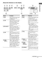
...activated. For details on the display 1 2 34 5 67 SW LFE SP A ; continued 7US PL II" lights up when using the receiver to the speaker system used. Lights up when the Pro Logic II Movie or Music decoder is selected. Getting Started About the indicators on presetting radio stations, see page...COAX 8 CAT MEMORY ST D.RANGE MONO qd qs qa q; 9 Name A SW B LFE C SP A/SP B D ;D E ;PL/ ;PL II Function Lights up if the speaker output is turned off or if a headphone is a digital signal being played back contains an LFE (Low Frequency Effect) channel and the LFE channel signal...
...activated. For details on the display 1 2 34 5 67 SW LFE SP A ; continued 7US PL II" lights up when using the receiver to the speaker system used. Lights up when the Pro Logic II Movie or Music decoder is selected. Getting Started About the indicators on presetting radio stations, see page...COAX 8 CAT MEMORY ST D.RANGE MONO qd qs qa q; 9 Name A SW B LFE C SP A/SP B D ;D E ;PL/ ;PL II Function Lights up if the speaker output is turned off or if a headphone is a digital signal being played back contains an LFE (Low Frequency Effect) channel and the LFE channel signal...
Operating Instructions
Page 9
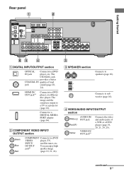
...sound are output to speakers (page 16). OUTPUT jacka) You can enjoy high quality image (page 19, 21, 24). 3 C SPEAKER section Connects to a TV or a projector (page 22). Connects to a DIGITAL MEDIA PORT adapter (page 64). Connect to sub woofer (page 16). B COMPONENT VIDEO INPUT/ OUTPUT ...section Green Blue Red COMPONENT Connects to a DVD player, or a Blu-ray disc ...
...sound are output to speakers (page 16). OUTPUT jacka) You can enjoy high quality image (page 19, 21, 24). 3 C SPEAKER section Connects to a TV or a projector (page 22). Connects to a DIGITAL MEDIA PORT adapter (page 64). Connect to sub woofer (page 16). B COMPONENT VIDEO INPUT/ OUTPUT ...section Green Blue Red COMPONENT Connects to a DVD player, or a Blu-ray disc ...
Operating Instructions
Page 12
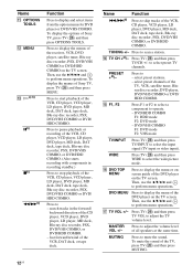
...Blu-ray disc recorder, PSX, DVD/VHS COMBO, or DVD/HDD COMBO. (Also starts recording with components in the forward/ backward direction of Sony TV, press TV (Z) and then press OPTIONS TOOLS. fast forward/rewind of all speakers at the same time. N TV CH +a)/- Then, use the V/v/B/b and to stop playback of ... TV volume level. Press TV (Z) and then press TV VOL to select the input signal (TV input or video input). To mute the sound of Sony TV, press TV (Z) and then press MENU. TUNING +/- Name K OPTIONS TOOLS L MENU M Ha) b) Xb) xb) m/Mb) Function Press to display the menus of...
...Blu-ray disc recorder, PSX, DVD/VHS COMBO, or DVD/HDD COMBO. (Also starts recording with components in the forward/ backward direction of Sony TV, press TV (Z) and then press OPTIONS TOOLS. fast forward/rewind of all speakers at the same time. N TV CH +a)/- Then, use the V/v/B/b and to stop playback of ... TV volume level. Press TV (Z) and then press TV VOL to select the input signal (TV input or video input). To mute the sound of Sony TV, press TV (Z) and then press MENU. TUNING +/- Name K OPTIONS TOOLS L MENU M Ha) b) Xb) xb) m/Mb) Function Press to display the menus of...

Operating Instructions
Page 14
... shown in certain countries). 1: Installing speakers To fully enjoy theater-like multi channel surround sound requires five speakers (two front speakers, a center speaker, and two surround speakers) and a sub woofer (5.1 channel). Example of a 5.1 channel speaker system configuration Installing the speakers on the speaker stand For greater flexibility in positioning the speakers, use the optional WS-FV11 speaker stand (available only in the...
... shown in certain countries). 1: Installing speakers To fully enjoy theater-like multi channel surround sound requires five speakers (two front speakers, a center speaker, and two surround speakers) and a sub woofer (5.1 channel). Example of a 5.1 channel speaker system configuration Installing the speakers on the speaker stand For greater flexibility in positioning the speakers, use the optional WS-FV11 speaker stand (available only in the...

Operating Instructions
Page 15
...that are suitable for the wall material and strength. Install the speakers on a vertical and flat wall where reinforcement is applied. • Contact a screw shop or installer regarding the wall material or screws to be used. • Sony is especially fragile, attach the screws securely to a beam and... fasten them to 7 mm. 3 Hang the speakers on the back of each speaker as shown in the illustrations below. The screws should protrude 5 to the wall...
...that are suitable for the wall material and strength. Install the speakers on a vertical and flat wall where reinforcement is applied. • Contact a screw shop or installer regarding the wall material or screws to be used. • Sony is especially fragile, attach the screws securely to a beam and... fasten them to 7 mm. 3 Hang the speakers on the back of each speaker as shown in the illustrations below. The screws should protrude 5 to the wall...
Operating Instructions
Page 16
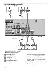
... speaker system" (page 28). b)Use the long speaker cords to connect the surround speakers and the short speaker cords to the SPEAKERS FRONT B terminal. 2: Connecting speakers F A D A B DVD IN VIDEO 2/BD IN OUT HDMI Y XM PB/CB PR/CR VIDEO IN VIDEO IN VIDEO OUT VIDEO IN VIDEO OUT SAT IN DVD IN VIDEO 1 IN MONITOR OUT L MONITOR COMPONENT...
... speaker system" (page 28). b)Use the long speaker cords to connect the surround speakers and the short speaker cords to the SPEAKERS FRONT B terminal. 2: Connecting speakers F A D A B DVD IN VIDEO 2/BD IN OUT HDMI Y XM PB/CB PR/CR VIDEO IN VIDEO IN VIDEO OUT VIDEO IN VIDEO OUT SAT IN DVD IN VIDEO 1 IN MONITOR OUT L MONITOR COMPONENT...
Operating Instructions
Page 17
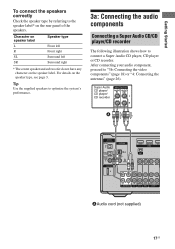
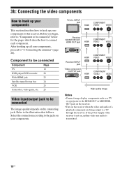
Tip Use the supplied speakers to optimize the system's performance. 3a: Connecting the audio components Connecting a Super Audio CD/CD player/CD recorder The following illustration shows how to "3b: Connecting the video components" (page 18) or "4: Connecting the antennas" (page 26). After connecting your audio component, proceed to connect a Super Audio CD player, CD player...
Tip Use the supplied speakers to optimize the system's performance. 3a: Connecting the audio components Connecting a Super Audio CD/CD player/CD recorder The following illustration shows how to "3b: Connecting the video components" (page 18) or "4: Connecting the antennas" (page 26). After connecting your audio component, proceed to connect a Super Audio CD player, CD player...
Operating Instructions
Page 18
... when the video and audio of the receiver is transmitted. 18US Select the connection according to connect each component. INPUT jack HDMI COMPONENT VIDEO VIDEO Receiver MONITOR OUT, HDMI OUT jack HDMI COMPONENT VIDEO VIDEO ? / 1 SPEAKERS (OFF/A/B/A+B) AUTO CAL MIC PHONES VIDEO 3 IN/PORTABLE AV IN VIDEO L AUDIO R MULTI CHANNEL DECODING DISPLAY INPUT MODE...
... when the video and audio of the receiver is transmitted. 18US Select the connection according to connect each component. INPUT jack HDMI COMPONENT VIDEO VIDEO Receiver MONITOR OUT, HDMI OUT jack HDMI COMPONENT VIDEO VIDEO ? / 1 SPEAKERS (OFF/A/B/A+B) AUTO CAL MIC PHONES VIDEO 3 IN/PORTABLE AV IN VIDEO L AUDIO R MULTI CHANNEL DECODING DISPLAY INPUT MODE...

Operating Instructions
Page 19
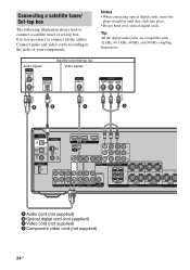
connect the audio output jacks of the TV to the TV IN jack of your components. Getting Started Connecting a TV The image from the speakers connected to the receiver, be displayed on , neither video nor audio is transmitted. turn off or mute the TV's volume. ...AUDIO IN SAT DVD R AUDIO OUT AUDIO IN VIDEO 1 SUB WOOFER FRONT B R FRONT A SPEAKERS L R SURROUND CENTER A Audio cord (not supplied) B Video cord (not supplied) C Component video cord (not supplied) Notes • Connect image display components such as a TV or a projector to the MONITOR OUT jack on the receiver. • ...
connect the audio output jacks of the TV to the TV IN jack of your components. Getting Started Connecting a TV The image from the speakers connected to the receiver, be displayed on , neither video nor audio is transmitted. turn off or mute the TV's volume. ...AUDIO IN SAT DVD R AUDIO OUT AUDIO IN VIDEO 1 SUB WOOFER FRONT B R FRONT A SPEAKERS L R SURROUND CENTER A Audio cord (not supplied) B Video cord (not supplied) C Component video cord (not supplied) Notes • Connect image display components such as a TV or a projector to the MONITOR OUT jack on the receiver. • ...
Operating Instructions
Page 20
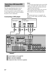
... HDMI Y XM PB/CB PR/CR VIDEO IN VIDEO IN VIDEO OUT VIDEO IN VIDEO OUT SAT IN DVD IN VIDEO 1 IN MONITOR OUT L MONITOR COMPONENT VIDEO R L L L L L AUDIO OUT R R OUT IN IN SA-CD/CD/CD-R TV R AUDIO IN AUDIO IN SAT DVD R AUDIO OUT AUDIO IN VIDEO 1... SUB WOOFER FRONT B R FRONT A SPEAKERS L R SURROUND CENTER A Coaxial digital cord (supplied) B Audio cord (not supplied) C Video cord (not supplied) D Component video cord (not supplied) 20US Tip All the digital audio jacks are compatible with the DVD player. •...
... HDMI Y XM PB/CB PR/CR VIDEO IN VIDEO IN VIDEO OUT VIDEO IN VIDEO OUT SAT IN DVD IN VIDEO 1 IN MONITOR OUT L MONITOR COMPONENT VIDEO R L L L L L AUDIO OUT R R OUT IN IN SA-CD/CD/CD-R TV R AUDIO IN AUDIO IN SAT DVD R AUDIO OUT AUDIO IN VIDEO 1... SUB WOOFER FRONT B R FRONT A SPEAKERS L R SURROUND CENTER A Coaxial digital cord (supplied) B Audio cord (not supplied) C Video cord (not supplied) D Component video cord (not supplied) 20US Tip All the digital audio jacks are compatible with the DVD player. •...
Operating Instructions
Page 21
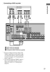
... HDMI Y XM PB/CB PR/CR VIDEO IN VIDEO IN VIDEO OUT VIDEO IN VIDEO OUT SAT IN DVD IN VIDEO 1 IN MONITOR OUT L MONITOR COMPONENT VIDEO R L L L L L AUDIO OUT R R OUT IN IN SA-CD/CD/CD-R TV R AUDIO IN AUDIO IN SAT DVD R AUDIO OUT AUDIO IN VIDEO 1 SUB WOOFER... FRONT B R FRONT A SPEAKERS L R SURROUND CENTER A Audio cord (not supplied) B Video cord (not supplied) C Component video cord (not supplied) • Be sure to change the factory setting of the VIDEO 1 input button on the receiver...
... HDMI Y XM PB/CB PR/CR VIDEO IN VIDEO IN VIDEO OUT VIDEO IN VIDEO OUT SAT IN DVD IN VIDEO 1 IN MONITOR OUT L MONITOR COMPONENT VIDEO R L L L L L AUDIO OUT R R OUT IN IN SA-CD/CD/CD-R TV R AUDIO IN AUDIO IN SAT DVD R AUDIO OUT AUDIO IN VIDEO 1 SUB WOOFER... FRONT B R FRONT A SPEAKERS L R SURROUND CENTER A Audio cord (not supplied) B Video cord (not supplied) C Component video cord (not supplied) • Be sure to change the factory setting of the VIDEO 1 input button on the receiver...
Operating Instructions
Page 22
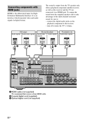
...DVD R AUDIO OUT AUDIO IN VIDEO 1 SUB WOOFER FRONT B R FRONT A SPEAKERS L R SURROUND CENTER A HDMI cable (not supplied) We recommend that you use a Sony HDMI cable. It is output from the supplied speakers and to take advantage of the multi channel surround sound, be sure to the receiver.... - DVD player Audio signals Audio/video signals Blu-ray disc player Audio/video signals Audio signals TV, projector, etc. Connecting components...
...DVD R AUDIO OUT AUDIO IN VIDEO 1 SUB WOOFER FRONT B R FRONT A SPEAKERS L R SURROUND CENTER A HDMI cable (not supplied) We recommend that you use a Sony HDMI cable. It is output from the supplied speakers and to take advantage of the multi channel surround sound, be sure to the receiver.... - DVD player Audio signals Audio/video signals Blu-ray disc player Audio/video signals Audio signals TV, projector, etc. Connecting components...
Operating Instructions
Page 24
... HDMI Y XM PB/CB PR/CR VIDEO IN VIDEO IN VIDEO OUT VIDEO IN VIDEO OUT SAT IN DVD IN VIDEO 1 IN MONITOR OUT L MONITOR COMPONENT VIDEO R L L L L L AUDIO OUT R R OUT IN IN SA-CD/CD/CD-R TV R AUDIO IN AUDIO IN SAT DVD R AUDIO OUT AUDIO IN VIDEO 1 ...SUB WOOFER FRONT B R FRONT A SPEAKERS L R SURROUND CENTER A Audio cord (not supplied) B Optical digital cord (not supplied) C Video cord (not supplied) D Component video cord (not supplied) 24US Tip All the digital audio jacks are compatible with 32 kHz, 44.1 kHz...
... HDMI Y XM PB/CB PR/CR VIDEO IN VIDEO IN VIDEO OUT VIDEO IN VIDEO OUT SAT IN DVD IN VIDEO 1 IN MONITOR OUT L MONITOR COMPONENT VIDEO R L L L L L AUDIO OUT R R OUT IN IN SA-CD/CD/CD-R TV R AUDIO IN AUDIO IN SAT DVD R AUDIO OUT AUDIO IN VIDEO 1 ...SUB WOOFER FRONT B R FRONT A SPEAKERS L R SURROUND CENTER A Audio cord (not supplied) B Optical digital cord (not supplied) C Video cord (not supplied) D Component video cord (not supplied) 24US Tip All the digital audio jacks are compatible with 32 kHz, 44.1 kHz...

Operating Instructions
Page 25
... HDMI Y XM PB/CB PR/CR VIDEO IN VIDEO IN VIDEO OUT VIDEO IN VIDEO OUT SAT IN DVD IN VIDEO 1 IN MONITOR OUT L MONITOR COMPONENT VIDEO R L L L L L AUDIO OUT R R OUT IN IN SA-CD/CD/CD-R TV R AUDIO IN AUDIO IN SAT DVD R AUDIO OUT AUDIO IN VIDEO 1 SUB ...WOOFER FRONT B R FRONT A SPEAKERS L R SURROUND CENTER To the VIDEO 3 IN/PORTABLE AV IN jacks (Front panel) Camcorder/ video game C A Audio cord (not supplied) B Video cord (not supplied) C Audio/video...
... HDMI Y XM PB/CB PR/CR VIDEO IN VIDEO IN VIDEO OUT VIDEO IN VIDEO OUT SAT IN DVD IN VIDEO 1 IN MONITOR OUT L MONITOR COMPONENT VIDEO R L L L L L AUDIO OUT R R OUT IN IN SA-CD/CD/CD-R TV R AUDIO IN AUDIO IN SAT DVD R AUDIO OUT AUDIO IN VIDEO 1 SUB ...WOOFER FRONT B R FRONT A SPEAKERS L R SURROUND CENTER To the VIDEO 3 IN/PORTABLE AV IN jacks (Front panel) Camcorder/ video game C A Audio cord (not supplied) B Video cord (not supplied) C Audio/video...

Operating Instructions
Page 26
... L L L AUDIO OUT R R OUT IN IN SA-CD/CD/CD-R TV R AUDIO IN AUDIO IN SAT DVD R AUDIO OUT AUDIO IN VIDEO 1 SUB WOOFER FRONT B R FRONT A SPEAKERS L R SURROUND CENTER * The shape of the connector varies depending on the area code of this receiver. Notes • To prevent noise pickup, keep the AM... loop antenna away from the receiver and other components. • Be sure to fully extend the FM wire antenna. • After connecting the FM wire antenna, keep it as horizontal as possible....
... L L L AUDIO OUT R R OUT IN IN SA-CD/CD/CD-R TV R AUDIO IN AUDIO IN SAT DVD R AUDIO OUT AUDIO IN VIDEO 1 SUB WOOFER FRONT B R FRONT A SPEAKERS L R SURROUND CENTER * The shape of the connector varies depending on the area code of this receiver. Notes • To prevent noise pickup, keep the AM... loop antenna away from the receiver and other components. • Be sure to fully extend the FM wire antenna. • After connecting the FM wire antenna, keep it as horizontal as possible....
Operating Instructions
Page 27
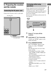
...AUTO CAL MUTING 3 1 Press ?/1 to turn off the receiver. 2 Hold down ?/1 for this operation. 1,2 CENTER To the wall outlet ? / 1 SPEAKERS (OFF/A/B/A+B) AUTO CAL MIC PHONES VIDEO 3 IN/PORTABLE AV IN VIDEO L AUDIO R MULTI CHANNEL DECODING DISPLAY INPUT MODE INPUT SELECTOR MASTER VOLUME MEMORY/ ENTER ...used to return settings you have made to their factory settings. • All settings in the LEVEL, TONE, SUR, TUNER, AUDIO, VIDEO and SYSTEM menus. • The sound field memorized for each input and preset station. • All sound field parameters. • All preset stations. ...
...AUTO CAL MUTING 3 1 Press ?/1 to turn off the receiver. 2 Hold down ?/1 for this operation. 1,2 CENTER To the wall outlet ? / 1 SPEAKERS (OFF/A/B/A+B) AUTO CAL MIC PHONES VIDEO 3 IN/PORTABLE AV IN VIDEO L AUDIO R MULTI CHANNEL DECODING DISPLAY INPUT MODE INPUT SELECTOR MASTER VOLUME MEMORY/ ENTER ...used to return settings you have made to their factory settings. • All settings in the LEVEL, TONE, SUR, TUNER, AUDIO, VIDEO and SYSTEM menus. • The sound field memorized for each input and preset station. • All sound field parameters. • All preset stations. ...


