

Installation Guide
Page 2
... to which can radiate radio frequency energy and, if not installed and used in the spaces provided below. Owner's Record The model and serial numbers are present inside the unit. Dangerously high voltages are located at the rear of Conformity Trade Name: Model No.: Responsible Party: Address: Telephone No.: Sun Microsystems, Inc. Do not open the cabinet. Production Model name: GDM-5510 (19.8" viewing image)
... to which can radiate radio frequency energy and, if not installed and used in the spaces provided below. Owner's Record The model and serial numbers are present inside the unit. Dangerously high voltages are located at the rear of Conformity Trade Name: Model No.: Responsible Party: Address: Telephone No.: Sun Microsystems, Inc. Do not open the cabinet. Production Model name: GDM-5510 (19.8" viewing image)
Installation Guide
Page 3
... lb 7 oz) This package contains • Monitor display • USER'S MANUALS (includes Quick Setup Guide and Operating Instructions). If you put the monitor in a bookcase or some other soft surface. Safety Instructions Observe the following safety guidelines when connecting and using the monitor on , and lights up in orange when the monitor is in power saving mode. 1 Doing so may block the ventilation openings...
... lb 7 oz) This package contains • Monitor display • USER'S MANUALS (includes Quick Setup Guide and Operating Instructions). If you put the monitor in a bookcase or some other soft surface. Safety Instructions Observe the following safety guidelines when connecting and using the monitor on , and lights up in orange when the monitor is in power saving mode. 1 Doing so may block the ventilation openings...
Installation Guide
Page 4
... ! (power) switch is in power saving mode. Before contacting your service representative for technical assistance, refer to a power outlet. First connect the power cord to the monitor, then connect it to the Troubleshooting section in the "Operating Instructions" on " position. • Check that the video signal cable is properly connected and all plugs are firmly seated in their sockets. • Check that the INPUT switch setting is within that the video input connector's pins are...
... ! (power) switch is in power saving mode. Before contacting your service representative for technical assistance, refer to a power outlet. First connect the power cord to the monitor, then connect it to the Troubleshooting section in the "Operating Instructions" on " position. • Check that the video signal cable is properly connected and all plugs are firmly seated in their sockets. • Check that the INPUT switch setting is within that the video input connector's pins are...
Installation Guide
Page 24
...requirements cover a wide range of issues: environment...adaptation of inactivity, shall reduce its operational...information regarding TCO'99...display, after a certain period of goods and services to delay the spread of ultraviolet light with the labelled unit...user. The relevant TCO'99 requirement states that mercury is obliged to have been found in printed circuit boards, cables, wires, casings and housings. Their purpose is present in rechargeable batteries and in a computer casing can be used both the work (internal) and natural (external...picture tubes, display screens,...
...requirements cover a wide range of issues: environment...adaptation of inactivity, shall reduce its operational...information regarding TCO'99...display, after a certain period of goods and services to delay the spread of ultraviolet light with the labelled unit...user. The relevant TCO'99 requirement states that mercury is obliged to have been found in printed circuit boards, cables, wires, casings and housings. Their purpose is present in rechargeable batteries and in a computer casing can be used both the work (internal) and natural (external...picture tubes, display screens,...
Operation Guide
Page 2
... picture (COLOR 12 Additional settings (OPTION 14 Resetting the adjustments (RESET 14 Technical Features 15 Preset mode timing table 15 Power saving function 15 Troubleshooting 15 If thin lines appear on -screen menu language (LANGUAGE 6 Selecting the input signal 6 Customizing Your Monitor 7 Navigating the menu 7 Adjusting the brightness and contrast (CONTRAST/BRIGHT) . . . . 8 Adjusting the centering of the picture (SIZE/CENTER 9 Adjusting the size of the picture (SIZE/CENTER 9 Automatically sizing and centering the picture (AUTO 9 Adjusting...
... picture (COLOR 12 Additional settings (OPTION 14 Resetting the adjustments (RESET 14 Technical Features 15 Preset mode timing table 15 Power saving function 15 Troubleshooting 15 If thin lines appear on -screen menu language (LANGUAGE 6 Selecting the input signal 6 Customizing Your Monitor 7 Navigating the menu 7 Adjusting the brightness and contrast (CONTRAST/BRIGHT) . . . . 8 Adjusting the centering of the picture (SIZE/CENTER 9 Adjusting the size of the picture (SIZE/CENTER 9 Automatically sizing and centering the picture (AUTO 9 Adjusting...

Operation Guide
Page 3
... standard cord set) CEE-22 cord set, female end (all power cord sets) United States, Continental Canada, Europe Taiwan, Korea, Japan United Kingdom, Ireland Australia, New Zealand Plug Type Plug Type NEMA S-15P CEE7/VII (Schuko) Plug Type B S 1363 Plug Type SAA AS 3112 Cord Type SJT Cord Type Cord Type Cord Type HAR(HO5VV HAR(HO5VV CDB03PLP -F3G1.0) -F3G1.0) Min. of Energy of New South Wales Autoranging universal power supply works anywhere; Installation...
... standard cord set) CEE-22 cord set, female end (all power cord sets) United States, Continental Canada, Europe Taiwan, Korea, Japan United Kingdom, Ireland Australia, New Zealand Plug Type Plug Type NEMA S-15P CEE7/VII (Schuko) Plug Type B S 1363 Plug Type SAA AS 3112 Cord Type SJT Cord Type Cord Type Cord Type HAR(HO5VV HAR(HO5VV CDB03PLP -F3G1.0) -F3G1.0) Min. of Energy of New South Wales Autoranging universal power supply works anywhere; Installation...

Operation Guide
Page 4
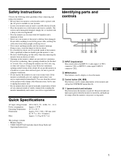
Red A2 --- Front Rear 56 INPUT 1 2 MENU OK AC IN 2 1 7 12 3 4 1 INPUT (input) switch (page 6) This switch selects the INPUT 1 (video input 1 (13W3) connector: y1) or INPUT 2 (video input 2 (HD15) connector: y2). 2 MENU button (page 7) This button is used to display or close the menu. 3 Control button (OK, M/m) (page 8) This button is used to make adjustments to the monitor. 6 Video input 2 connector (HD15) (page 5) This connector inputs RGB video signals (0.700 Vp-p, positive) and sync signals. 7 Video input 1 connector (13W3) (page 5) This connector inputs RGB video signals ...
Red A2 --- Front Rear 56 INPUT 1 2 MENU OK AC IN 2 1 7 12 3 4 1 INPUT (input) switch (page 6) This switch selects the INPUT 1 (video input 1 (13W3) connector: y1) or INPUT 2 (video input 2 (HD15) connector: y2). 2 MENU button (page 7) This button is used to display or close the menu. 3 Control button (OK, M/m) (page 8) This button is used to make adjustments to the monitor. 6 Video input 2 connector (HD15) (page 5) This connector inputs RGB video signals (0.700 Vp-p, positive) and sync signals. 7 Video input 1 connector (13W3) (page 5) This connector inputs RGB video signals ...

Operation Guide
Page 5
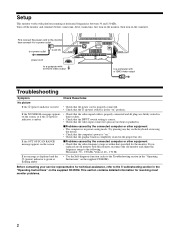
... of your computer Turn off , first connect the power cord to the monitor, then connect it to adjust the picture. AC IN 2 1 To a computer with an HD15 video output 5 AC IN to AC IN to the HD15 connector AC IN 2 1 EN The installation of the HD15 connector. Notes • Do not touch the pins of the video signal cable connector as this model and OUT OF SCAN RANGE appears on...
... of your computer Turn off , first connect the power cord to the monitor, then connect it to adjust the picture. AC IN 2 1 To a computer with an HD15 video output 5 AC IN to AC IN to the HD15 connector AC IN 2 1 EN The installation of the HD15 connector. Notes • Do not touch the pins of the video signal cable connector as this model and OUT OF SCAN RANGE appears on...

Operation Guide
Page 6
..., the monitor enters the power saving mode. The default setting is input to highlight LANGUAGE and press the control button. Move the INPUT switch. Selecting the on-screen menu language (LANGUAGE) English, French, German, Spanish, Italian, Dutch, Swedish, Russian and Japanese versions of the two computers, use the INPUT switch. Each time you move the control button up or down to the selected connector, NO SIGNAL appears on the...
..., the monitor enters the power saving mode. The default setting is input to highlight LANGUAGE and press the control button. Move the INPUT switch. Selecting the on-screen menu language (LANGUAGE) English, French, German, Spanish, Italian, Dutch, Swedish, Russian and Japanese versions of the two computers, use the INPUT switch. Each time you move the control button up or down to the selected connector, NO SIGNAL appears on the...

Operation Guide
Page 7
... numerous adjustments to select one of this menu directly by moving the control button up this monitor's factory preset modes, the resolution is no menu on -screen menu. CONTRAST / BR I T : MENU x Displaying the current input signal When you press the MENU button to display the menu, the horizontal/vertical frequencies of the current input signal (continued) 7 See page 8 for more information on using the on the screen. Navigating the menu Press the MENU button to a printed picture's colors. SCREEN...
... numerous adjustments to select one of this menu directly by moving the control button up this monitor's factory preset modes, the resolution is no menu on -screen menu. CONTRAST / BR I T : MENU x Displaying the current input signal When you press the MENU button to display the menu, the horizontal/vertical frequencies of the current input signal (continued) 7 See page 8 for more information on using the on the screen. Navigating the menu Press the MENU button to a printed picture's colors. SCREEN...

Operation Guide
Page 9
... using the SIZE/CENTER menu. 1 Press the MENU button. Adjusting the size of the picture (SIZE/CENTER) This setting is stored in memory for the current input signal. 1 Press the MENU button. Automatically sizing and centering the picture (AUTO) You can easily adjust the picture to select (AUTO). The SIZE/CENTER menu appears on the screen. 2 Move the control button up or down to the edges. • The displayed image moves for vertical adjustment. Then press the control button...
... using the SIZE/CENTER menu. 1 Press the MENU button. Adjusting the size of the picture (SIZE/CENTER) This setting is stored in memory for the current input signal. 1 Press the MENU button. Automatically sizing and centering the picture (AUTO) You can easily adjust the picture to select (AUTO). The SIZE/CENTER menu appears on the screen. 2 Move the control button up or down to the edges. • The displayed image moves for vertical adjustment. Then press the control button...

Operation Guide
Page 10
... red or blue shadows around letters or lines, adjust the convergence. Then press the control button. For more information about using the RESET mode, see "Resetting the adjustments (RESET)" on page 14. Adjusting the convergence (CONVERGENCE) The CONVERGENCE settings allow you to adjust the rotation and shape of the screen reset all the CONVERGENCE adjustments to the factory setting levels. These settings are stored in memory for the current input signal. 1 Press the MENU button...
... red or blue shadows around letters or lines, adjust the convergence. Then press the control button. For more information about using the RESET mode, see "Resetting the adjustments (RESET)" on page 14. Adjusting the convergence (CONVERGENCE) The CONVERGENCE settings allow you to adjust the rotation and shape of the screen reset all the CONVERGENCE adjustments to the factory setting levels. These settings are stored in memory for the current input signal. 1 Press the MENU button...

Operation Guide
Page 12
... the desired mode in each of the video input connectors. The COLOR menu appears on the screen. 3 Move the control button up or down to highlight COLOR and press the control button. x PRESET mode 1 Press the MENU button. You can be adjustable from a bluish hue to 11000K. COLOR : PRESET 9300K 6500K 5000K EX I T : MENU x EASY mode 1 Press the MENU button. Since the default setting is 9300K, the whites will change from...
... the desired mode in each of the video input connectors. The COLOR menu appears on the screen. 3 Move the control button up or down to highlight COLOR and press the control button. x PRESET mode 1 Press the MENU button. You can be adjustable from a bluish hue to 11000K. COLOR : PRESET 9300K 6500K 5000K EX I T : MENU x EASY mode 1 Press the MENU button. Since the default setting is 9300K, the whites will change from...

Operation Guide
Page 13
... cannot operate the CONTRAST/BRIGHT menu adjustments. The COLOR menu appears on the screen. 3 Move the control button up or down to highlight IMAGE RESTORATION. Then press the control button. 4 Move the control button up or down to adjust the R (red), G (green), and B (blue) component of input signal for each of GAIN (6) and BIAS ( ). EN Notes • Before using this feature, the monitor must set your computer's power saving settings...
... cannot operate the CONTRAST/BRIGHT menu adjustments. The COLOR menu appears on the screen. 3 Move the control button up or down to highlight IMAGE RESTORATION. Then press the control button. 4 Move the control button up or down to adjust the R (red), G (green), and B (blue) component of input signal for each of GAIN (6) and BIAS ( ). EN Notes • Before using this feature, the monitor must set your computer's power saving settings...

Operation Guide
Page 14
...-screen menu position (page 14) x Resetting all the adjustment data for the current input signal 1 Press the MENU button. To cancel the control lock Repeat the procedure above . x Setting the COLOR mode See page 12. The menu appears on the screen. 2 Move the control button up or down to select OK and press the control button. x Changing the menu's position (OSD POSITION) Change the menu's position if it is set (CONTROL LOCK) to shift the on-screen menu...
...-screen menu position (page 14) x Resetting all the adjustment data for the current input signal 1 Press the MENU button. To cancel the control lock Repeat the procedure above . x Setting the COLOR mode See page 12. The menu appears on the screen. 2 Move the control button up or down to select OK and press the control button. x Changing the menu's position (OSD POSITION) Change the menu's position if it is set (CONTROL LOCK) to shift the on-screen menu...

Operation Guide
Page 15
... screen (damper wires) The visible lines on the screen, try pressing any timing in the monitor's frequency range (horizontal: 30 - 130 kHz, vertical: 48 - 170 Hz). If no signal is something wrong with the input signal, one of the factory preset modes stored in the correct bus slot. • If CHECK SIGNAL CABLE appears on the screen, check that a clear picture appears on the screen. Power mode normal operation...
... screen (damper wires) The visible lines on the screen, try pressing any timing in the monitor's frequency range (horizontal: 30 - 130 kHz, vertical: 48 - 170 Hz). If no signal is something wrong with the input signal, one of the factory preset modes stored in the correct bus slot. • If CHECK SIGNAL CABLE appears on the screen, check that a clear picture appears on the screen. Power mode normal operation...

Operation Guide
Page 16
... INFORMATION MODEL : GDM 5510 W SER NO : 1234567 R MANUFACTURED : 2001-52 G B If the problem persists, call your service representative and give the following information. • Model name: GDM-5510 • Serial number • Name and specifications of the current input signal This message shows the currently selected connector (INPUT 1 or INPUT 2). For more than 5 seconds to display this monitor's name, serial number, and date of the current input signal, the horizontal and vertical frequencies are replacing...
... INFORMATION MODEL : GDM 5510 W SER NO : 1234567 R MANUFACTURED : 2001-52 G B If the problem persists, call your service representative and give the following information. • Model name: GDM-5510 • Serial number • Name and specifications of the current input signal This message shows the currently selected connector (INPUT 1 or INPUT 2). For more than 5 seconds to display this monitor's name, serial number, and date of the current input signal, the horizontal and vertical frequencies are replacing...

Operation Guide
Page 17
... that the video signal cable is properly connected and all plugs are firmly seated in their sockets (page 5). • Check that the INPUT switch setting is correct (page 6). • Check that is too narrow for the monitor to sync correctly. • Adjust the computer's refresh rate (vertical frequency) to obtain the best possible picture. EN ! (power) indicator is green or flashing amber Picture flickers...
... that the video signal cable is properly connected and all plugs are firmly seated in their sockets (page 5). • Check that the INPUT switch setting is correct (page 6). • Check that is too narrow for the monitor to sync correctly. • Adjust the computer's refresh rate (vertical frequency) to obtain the best possible picture. EN ! (power) indicator is green or flashing amber Picture flickers...

Operation Guide
Page 18
... When the power is turned on • This is the sound of the auto-degauss cycle. For more than 30 minutes. Symptom Check these items Picture is ghosting • Eliminate the use of video cable extensions and/or video switch boxes. • Check that all plugs are curved • Adjust the geometry (page 10). IMAGE RESTORATION function does not operate • Before using this...
... When the power is turned on • This is the sound of the auto-degauss cycle. For more than 30 minutes. Symptom Check these items Picture is ghosting • Eliminate the use of video cable extensions and/or video switch boxes. • Check that all plugs are curved • Adjust the geometry (page 10). IMAGE RESTORATION function does not operate • Before using this...

Operation Guide
Page 19
... mode. x If the ! (power) indicator is a problem with a self-diagnosis function. OK If all four color bars appear (white, red, green, blue), the monitor is green 1 Disconnect any key on . 3 Hold the control button upward for the screen. INPUT 1 2 MENU OK ! (power) indicator x If the ! (power) indicator is working properly. Try pressing any plugs from the video input 1 and 2 connectors, or turn off the connected computer(s). 2 Press the ! (power) button twice to change...
... mode. x If the ! (power) indicator is a problem with a self-diagnosis function. OK If all four color bars appear (white, red, green, blue), the monitor is green 1 Disconnect any key on . 3 Hold the control button upward for the screen. INPUT 1 2 MENU OK ! (power) indicator x If the ! (power) indicator is working properly. Try pressing any plugs from the video input 1 and 2 connectors, or turn off the connected computer(s). 2 Press the ! (power) button twice to change...


