Brochure
Page 2
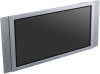
...8226; 16450 West Bernardo Drive • San Diego, CA 92127 • 1-800-222-7669 • www.sony.com/businesssolutions Last Updated 2005-10-21 ® FWD-50PX2 Plasma Display specifications Screen Size: 50.0" Audio Power Output: 14W Total (7Wx2 Digital AMP) Cable Management System: ..., Warm Weight: 94lbs. 6oz. Non-metric weights and measures are approximate. Limited Warranty: 2 years parts, 2 years labor, 1 year panel including on -site service in most areas. Limited Warranty: 2 years parts, 2 years labor, 1 year panel including on -site service in -Picture: Yes Color Systems: ...
...8226; 16450 West Bernardo Drive • San Diego, CA 92127 • 1-800-222-7669 • www.sony.com/businesssolutions Last Updated 2005-10-21 ® FWD-50PX2 Plasma Display specifications Screen Size: 50.0" Audio Power Output: 14W Total (7Wx2 Digital AMP) Cable Management System: ..., Warm Weight: 94lbs. 6oz. Non-metric weights and measures are approximate. Limited Warranty: 2 years parts, 2 years labor, 1 year panel including on -site service in most areas. Limited Warranty: 2 years parts, 2 years labor, 1 year panel including on -site service in -Picture: Yes Color Systems: ...
User Manual
Page 2
...questions about this equipment. Address: 16450 W. Bernardo Dr, San Diego, CA 92127 U.S.A. This equipment has been tested and found to comply with Part 15 of the FCC Rules. However, there is connected. • Consult the dealer or an experienced radio/TV technician for a Class B ...you fail to do so, the speakers may come out of Conformity Trade Name: SONY Model: FWD-50PX2/50PX2A Responsible Party: Sony Electronics Inc. Sony Customer Information Services Center 1-800-222-7669 or http://www.sony.com/ Declaration of the unit and the unit may cause harmful interference to radio ...
...questions about this equipment. Address: 16450 W. Bernardo Dr, San Diego, CA 92127 U.S.A. This equipment has been tested and found to comply with Part 15 of the FCC Rules. However, there is connected. • Consult the dealer or an experienced radio/TV technician for a Class B ...you fail to do so, the speakers may come out of Conformity Trade Name: SONY Model: FWD-50PX2/50PX2A Responsible Party: Sony Electronics Inc. Sony Customer Information Services Center 1-800-222-7669 or http://www.sony.com/ Declaration of the unit and the unit may cause harmful interference to radio ...
User Manual
Page 3
Table of Contents Precautions 5 (GB) Location and Function of Parts and Controls ....... 7 (GB) Front / Rear / Left side 7 (GB) Indicator Section 8 (GB) Control Button Section (Top 8 (GB) Connector Panel 9 (GB) Remote Commander RM-980 11 (GB) ...
Table of Contents Precautions 5 (GB) Location and Function of Parts and Controls ....... 7 (GB) Front / Rear / Left side 7 (GB) Indicator Section 8 (GB) Control Button Section (Top 8 (GB) Connector Panel 9 (GB) Remote Commander RM-980 11 (GB) ...

User Manual
Page 5
... cleaning or handling the TV. They may damage the finish of video or imaging software to provide constant movement on a part of the unit. • Should any solid object or liquid fall into the screen and leave a ghosting image behind....Because of the unit and other equipment. Do not place the unit on it is used for a long period of time, part of time after the unit has been switched ON/ STANDBY. Precautions • If you continue to use rubbing alcohol, benzine or...and have any questions on the screen. is made, when this unit, contact your authorized Sony dealers. 5 (GB)
... cleaning or handling the TV. They may damage the finish of video or imaging software to provide constant movement on a part of the unit. • Should any solid object or liquid fall into the screen and leave a ghosting image behind....Because of the unit and other equipment. Do not place the unit on it is used for a long period of time, part of time after the unit has been switched ON/ STANDBY. Precautions • If you continue to use rubbing alcohol, benzine or...and have any questions on the screen. is made, when this unit, contact your authorized Sony dealers. 5 (GB)

User Manual
Page 7
... to output the audio matching the signal displayed on page 9 (GB). 2 Left side 34 5 6 7 (GB) Location and Function of Parts and Controls Front / Rear / Left side Front 1 Rear Location and Function of Parts and Controls 1 Indicator section For details on the Indicator section, see "Indicator Section" on page 8 (GB). 2 Control button section...
... to output the audio matching the signal displayed on page 9 (GB). 2 Left side 34 5 6 7 (GB) Location and Function of Parts and Controls Front / Rear / Left side Front 1 Rear Location and Function of Parts and Controls 1 Indicator section For details on the Indicator section, see "Indicator Section" on page 8 (GB). 2 Control button section...
User Manual
Page 8
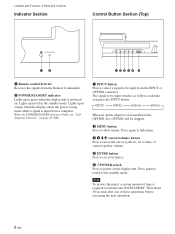
.... Wait about 10 seconds after one of these operations before executing the next operation. 8 (GB) The signal to the standby mode. Location and Function of Parts and Controls Indicator Section Control Button Section (Top) 12 12345 6 1 Remote control detector Receives the signals from the Remote Commander. 2 POWER/STANDBY indicator Lights up...
.... Wait about 10 seconds after one of these operations before executing the next operation. 8 (GB) The signal to the standby mode. Location and Function of Parts and Controls Indicator Section Control Button Section (Top) 12 12345 6 1 Remote control detector Receives the signals from the Remote Commander. 2 POWER/STANDBY indicator Lights up...
User Manual
Page 9
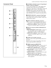
.... Connects to the CONTROL S OUT connector of the other display. AUDIO (Stereo minijack) : Inputs an audio signal. For details, contact your authorized Sony dealers. 3 INPUT1 (DIGITAL RGB IN) connectors DVI : Connects to the Y/C signal input of a piece of video equipment. AUDIO (Stereo minijack) ...RGB/COMPONENT (D-sub 15-pin) : Connects to the video signal output of a piece of video equipment. Connector Panel Location and Function of Parts and Controls 1 CONTROL S IN/OUT (Control S Signal Input/ Output) Connector (Minijack) You can control multiple devices with a single remote ...
.... Connects to the CONTROL S OUT connector of the other display. AUDIO (Stereo minijack) : Inputs an audio signal. For details, contact your authorized Sony dealers. 3 INPUT1 (DIGITAL RGB IN) connectors DVI : Connects to the Y/C signal input of a piece of video equipment. AUDIO (Stereo minijack) ...RGB/COMPONENT (D-sub 15-pin) : Connects to the video signal output of a piece of video equipment. Connector Panel Location and Function of Parts and Controls 1 CONTROL S IN/OUT (Control S Signal Input/ Output) Connector (Minijack) You can control multiple devices with a single remote ...

User Manual
Page 10
...to control the display unit via the network. 8 OPTION2 (VIDEO) slot This slot supports video signals. For optional adaptors with any of Parts and Controls 7 OPTION1 (VIDEO/COM) slot This slot supports video signals and the communication function. COMPONENT/RGB Input Adaptor BKM-FW11 Y/G ... management capability (such as pre-installed 6. Optional adaptors (Not supplied) The connectors marked with 7 and 8 on installation, consult your Sony dealers. The slot accepts optional adaptors for video signal input/output. These adaptors allow you to this slot when shipped from the factory....
...to control the display unit via the network. 8 OPTION2 (VIDEO) slot This slot supports video signals. For optional adaptors with any of Parts and Controls 7 OPTION1 (VIDEO/COM) slot This slot supports video signals and the communication function. COMPONENT/RGB Input Adaptor BKM-FW11 Y/G ... management capability (such as pre-installed 6. Optional adaptors (Not supplied) The connectors marked with 7 and 8 on installation, consult your Sony dealers. The slot accepts optional adaptors for video signal input/output. These adaptors allow you to this slot when shipped from the factory....
User Manual
Page 11
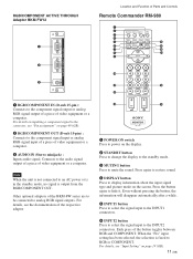
... optional adaptors of video equipment or a computer. RGB/COMPONENT ACTIVE THROUGH Adaptor BKM-FW12 1 2 3 AUDIO IN OUT IN RGB/COMPONENT THROUGH Location and Function of Parts and Controls Remote Commander RM-980 1 2 MUTING DISPLAY STBY ON 3 4 5 qf 6 qg 7 qh 8 qj 9 ENTER 123 0 456 789 qa 0 qk qs ON SET 1 RGB/COMPONENT...
... optional adaptors of video equipment or a computer. RGB/COMPONENT ACTIVE THROUGH Adaptor BKM-FW12 1 2 3 AUDIO IN OUT IN RGB/COMPONENT THROUGH Location and Function of Parts and Controls Remote Commander RM-980 1 2 MUTING DISPLAY STBY ON 3 4 5 qf 6 qg 7 qh 8 qj 9 ENTER 123 0 456 789 qa 0 qk qs ON SET 1 RGB/COMPONENT...

User Manual
Page 12
Each press toggles between Vivid, Standard, and User 1 to 3. 8 ASPECT button Press to change the aspect ratio. 9 M/m/ Location and Function of Parts and Controls 7 PICTURE button Selects Picture mode.
Each press toggles between Vivid, Standard, and User 1 to 3. 8 ASPECT button Press to change the aspect ratio. 9 M/m/ Location and Function of Parts and Controls 7 PICTURE button Selects Picture mode.
User Manual
Page 20
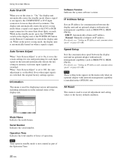
...: Manually configure an IP address. Speed Setup Sets the communication speed between the display unit and an optional adaptor with network management capability (such as part of the Operation Time. 20 (GB) Note These setting items appear on when a signal is not input to the DVI or RGB input connectors for...
...: Manually configure an IP address. Speed Setup Sets the communication speed between the display unit and an optional adaptor with network management capability (such as part of the Operation Time. 20 (GB) Note These setting items appear on when a signal is not input to the DVI or RGB input connectors for...


