Operating Instructions
Page 1
4-681-446-19(1) AIT Drive Operating Instructions AIT-5 TAPE DRIVE AITe1040/AITe1040V AIT-4 TAPE DRIVE AITe520/AITe520V AIT-3 Ex TAPE DRIVE AITe390/AITe390V AIT-3 TAPE DRIVE AITe260/AITe260V AIT-2 TAPE DRIVE AITe130/AITe130V AIT-1 TAPE DRIVE AITe90/AITe90V ©2003 Sony Corporation
4-681-446-19(1) AIT Drive Operating Instructions AIT-5 TAPE DRIVE AITe1040/AITe1040V AIT-4 TAPE DRIVE AITe520/AITe520V AIT-3 Ex TAPE DRIVE AITe390/AITe390V AIT-3 TAPE DRIVE AITe260/AITe260V AIT-2 TAPE DRIVE AITe130/AITe130V AIT-1 TAPE DRIVE AITe90/AITe90V ©2003 Sony Corporation
Operating Instructions
Page 2
... rated voltage and current. Safety Regulations Owner's Record The model and serial numbers are cautioned that any changes or modifications not expressly approved in this manual could void your authority to operate this equipment. Refer to correct the interference by one or more of fire or electric shock, do not open the cabinet. Refer servicing to rain or moisture. Your...
... rated voltage and current. Safety Regulations Owner's Record The model and serial numbers are cautioned that any changes or modifications not expressly approved in this manual could void your authority to operate this equipment. Refer to correct the interference by one or more of fire or electric shock, do not open the cabinet. Refer servicing to rain or moisture. Your...

Operating Instructions
Page 6
... the operating instructions. Improper adjustment of the unit, and to protect it , paying particular attention to the plugs, receptacles, and the point where the cord exits from the wall outlet and refer servicing to be blocked or covered. • Never cover the slots and openings with a cloth or other hazards. Refer to all servicing to service the unit yourself as...
... the operating instructions. Improper adjustment of the unit, and to protect it , paying particular attention to the plugs, receptacles, and the point where the cord exits from the wall outlet and refer servicing to be blocked or covered. • Never cover the slots and openings with a cloth or other hazards. Refer to all servicing to service the unit yourself as...
Operating Instructions
Page 7
... SCSI ID Setting 18 Option Switches (DIP Switch 19 How To Use the AIT Drive 24 Cartridge Removal 25 Attaching the Dust Cover 26 WORM Function 28 Taking Care of the Drive 30 Safety Considerations 30 Avoiding Damage 30 Taking Care of Cartridges 32 Use Precautions 32 Storage Precautions 32 Cleaning 33 How To Clean 33 Specifications (AITe1040/AITe1040V 34 Specifications (AITe520/AITe520V 35 Specifications (AITe390/AITe390V 36 Specifications (AITe260...
... SCSI ID Setting 18 Option Switches (DIP Switch 19 How To Use the AIT Drive 24 Cartridge Removal 25 Attaching the Dust Cover 26 WORM Function 28 Taking Care of the Drive 30 Safety Considerations 30 Avoiding Damage 30 Taking Care of Cartridges 32 Use Precautions 32 Storage Precautions 32 Cleaning 33 How To Clean 33 Specifications (AITe1040/AITe1040V 34 Specifications (AITe520/AITe520V 35 Specifications (AITe390/AITe390V 36 Specifications (AITe260...
Operating Instructions
Page 8
... and remove cartridges. Read this part if you may need to use of the AITe1040/AITe1040V/ AITe520/AITe520V/AITe390/AITe390V/AITe260/AITe260V/AITe130/ AITe130V/AITe90/AITe90V drive. 8 How to operate the drive. How To Use This Guide This Guide describes the AITe1040/AITe1040V/AITe520/AITe520V/ AITe390/AITe390V/AITe260/AITe260V/AITe130/AITe130V/AITe90/ AITe90V drive, and how to clean the drive. If other SCSI devices are installing the drive...
... and remove cartridges. Read this part if you may need to use of the AITe1040/AITe1040V/ AITe520/AITe520V/AITe390/AITe390V/AITe260/AITe260V/AITe130/ AITe130V/AITe90/AITe90V drive. 8 How to operate the drive. How To Use This Guide This Guide describes the AITe1040/AITe1040V/AITe520/AITe520V/ AITe390/AITe390V/AITe260/AITe260V/AITe130/AITe130V/AITe90/ AITe90V drive, and how to clean the drive. If other SCSI devices are installing the drive...
Operating Instructions
Page 9
... Tape Drives are external AIT drive units that use data cartridges conforming to the AIT-4 format. The AITe260/AITe260V AIT-3 Tape Drives are external AIT drive units that use data cartridges conforming to the AIT-3 format. The AITe90/AITe90V AIT-1 Tape Drives are external AIT drive units that use data cartridges conforming to the AIT-1 format. Part 1. The AITe520/AITe520V drives support the AIT-4 and AIT-3 Ex format. Introduction About AIT Drives The AITe1040/AITe1040V AIT-5 Tape Drives are external AIT drive units that use data cartridges conforming to the AIT...
... Tape Drives are external AIT drive units that use data cartridges conforming to the AIT-4 format. The AITe260/AITe260V AIT-3 Tape Drives are external AIT drive units that use data cartridges conforming to the AIT-3 format. The AITe90/AITe90V AIT-1 Tape Drives are external AIT drive units that use data cartridges conforming to the AIT-1 format. Part 1. The AITe520/AITe520V drives support the AIT-4 and AIT-3 Ex format. Introduction About AIT Drives The AITe1040/AITe1040V AIT-5 Tape Drives are external AIT drive units that use data cartridges conforming to the AIT...

Operating Instructions
Page 10
... and data type. 10 Part 1. Introduction Features The AITe1040/AITe1040V drives have the following features: • Supports reading and writing to data cartridges conforming to the AIT-5, AIT-4, AIT-3 Ex, and AIT-3 formats. • Data compression provides 1,040 gigabytes of storage on SDX5-400C data cartridges.* The native capacity is 400 gigabytes of storage on SDX4-200C data cartridges. • Ultra 160 SCSI interface is fully supported for host computer access. •...
... and data type. 10 Part 1. Introduction Features The AITe1040/AITe1040V drives have the following features: • Supports reading and writing to data cartridges conforming to the AIT-5, AIT-4, AIT-3 Ex, and AIT-3 formats. • Data compression provides 1,040 gigabytes of storage on SDX5-400C data cartridges.* The native capacity is 400 gigabytes of storage on SDX4-200C data cartridges. • Ultra 160 SCSI interface is fully supported for host computer access. •...
Operating Instructions
Page 11
... SDX3-100C data cartridges. • Ultra 160 SCSI interface is fully supported for host computer access. • Fragment rewrite function (AIT-3 Ex) • Frame rewrite function (AIT-3) The AITe260/AITe260V drives have the following features: • Supports reading and writing to data cartridges conforming to the AIT-3, AIT-2, and AIT-1 formats. • Data compression provides 260 gigabytes of storage on SDX3X-150C data cartridges. • Ultra 160 SCSI interface is fully supported for host...
... SDX3-100C data cartridges. • Ultra 160 SCSI interface is fully supported for host computer access. • Fragment rewrite function (AIT-3 Ex) • Frame rewrite function (AIT-3) The AITe260/AITe260V drives have the following features: • Supports reading and writing to data cartridges conforming to the AIT-3, AIT-2, and AIT-1 formats. • Data compression provides 260 gigabytes of storage on SDX3X-150C data cartridges. • Ultra 160 SCSI interface is fully supported for host...

Operating Instructions
Page 12
... to data cartridges conforming to system environment and data type. 12 Part 1. The AITe130/AITe130V drives have the following features: • Supports reading and writing to data cartridges conforming to the AIT-2 and AIT-1 formats. • Data compression provides 130 gigabytes of storage on SDX2-50C data cartridges.* The native capacity is 50 gigabytes of storage on SDX2-50C data cartridges. • Wide Ultra SCSI (LVD/SE) interface is assuming 2.6 : 1 compression...
... to data cartridges conforming to system environment and data type. 12 Part 1. The AITe130/AITe130V drives have the following features: • Supports reading and writing to data cartridges conforming to the AIT-2 and AIT-1 formats. • Data compression provides 130 gigabytes of storage on SDX2-50C data cartridges.* The native capacity is 50 gigabytes of storage on SDX2-50C data cartridges. • Wide Ultra SCSI (LVD/SE) interface is assuming 2.6 : 1 compression...

Operating Instructions
Page 13
... different specifications and cannot be used with data cartridges marked with this drive. Introduction The AITe390/AITe390V drives can be used with data cartridges marked with the AIT-5, AIT-4, AIT-3 Ex, or AIT-3 logo. Compatible Data Cartridges The AITe1040/AITe1040V drives can be used with data cartridges marked with the AIT-3 Ex, AIT-3, AIT-2 Turbo, AIT-2 (read only), AIT-1 Turbo (read only), AIT-1 (read only), or AIT-E Turbo (read only) logo. The AITe260/AITe260V drives can damage the drive. The...
... different specifications and cannot be used with data cartridges marked with this drive. Introduction The AITe390/AITe390V drives can be used with data cartridges marked with the AIT-5, AIT-4, AIT-3 Ex, or AIT-3 logo. Compatible Data Cartridges The AITe1040/AITe1040V drives can be used with data cartridges marked with the AIT-3 Ex, AIT-3, AIT-2 Turbo, AIT-2 (read only), AIT-1 Turbo (read only), AIT-1 (read only), or AIT-E Turbo (read only) logo. The AITe260/AITe260V drives can damage the drive. The...

Operating Instructions
Page 15
... inserting and removing a AIT data cartridge. 2 POWER Indicator Lights while the drive is Not Completed Independent Independent Media Error Occurred H/W Error Occurred on Slow 1 pulse (0.9 sec on/0.3 sec off) Fast 1 pulse (0.3 sec on . 3 Dust Cover Prevents dust from entering the data cartridge receptacle. Introduction Part Names and Functions Front Panel 1 2 Advanced Intelligent Tape 34 5 6 1 AIT Data Cartridge Receptacle See page 24 to 25 for Drive Status The LED indicators are...
... inserting and removing a AIT data cartridge. 2 POWER Indicator Lights while the drive is Not Completed Independent Independent Media Error Occurred H/W Error Occurred on Slow 1 pulse (0.9 sec on/0.3 sec off) Fast 1 pulse (0.3 sec on . 3 Dust Cover Prevents dust from entering the data cartridge receptacle. Introduction Part Names and Functions Front Panel 1 2 Advanced Intelligent Tape 34 5 6 1 AIT Data Cartridge Receptacle See page 24 to 25 for Drive Status The LED indicators are...

Operating Instructions
Page 16
Introduction Rear Panel 5 EJECT Button Push to remove a data cartridge from the drive. 6 POWER Switch Press to turn the drive on or off. 1 2 3 4 1 Rotary Selector Switch SCSI ID selector. 2 AC IN Connector Connect the supplied power cable here. 3 SCSI Connector Connects to the SCSI interface of the host computer or peripheral device via a Wide SCSI cable. 4 Cooling Fan 16 Part 1.
Introduction Rear Panel 5 EJECT Button Push to remove a data cartridge from the drive. 6 POWER Switch Press to turn the drive on or off. 1 2 3 4 1 Rotary Selector Switch SCSI ID selector. 2 AC IN Connector Connect the supplied power cable here. 3 SCSI Connector Connects to the SCSI interface of the host computer or peripheral device via a Wide SCSI cable. 4 Cooling Fan 16 Part 1.

Operating Instructions
Page 17
...; AIT Drive Unit • Operating Instructions/Device Driver (CD-ROM) • Quick Start Guide • TapeCopy (CD-ROM) • Terminator • AIT data cartridge • Cleaning cartridge Notes • In addition to the box. 17 Part 2. Preparation Part 2. Preparation After you confirm that you first open the box, make sure it contains the following items. Contact your installation, connect the drive to the host computer, and select the SCSI ID...
...; AIT Drive Unit • Operating Instructions/Device Driver (CD-ROM) • Quick Start Guide • TapeCopy (CD-ROM) • Terminator • AIT data cartridge • Cleaning cartridge Notes • In addition to the box. 17 Part 2. Preparation Part 2. Preparation After you confirm that you first open the box, make sure it contains the following items. Contact your installation, connect the drive to the host computer, and select the SCSI ID...

Operating Instructions
Page 19
... details changing the DIP switch settings.) After changing the DIP switch settings, replace access cover and tighten the two slotted screws using the two original slotted screws provided. Once the DIP switch settings have been changed, replace the access cover using a slotted screwdriver. Remove the access cover to change the DIP switch settings. (Refer to change DIP switch settings on the drive, turn off the computer and disconnect the power cord from the unit. Preparation DIP Switch Access Cover...
... details changing the DIP switch settings.) After changing the DIP switch settings, replace access cover and tighten the two slotted screws using the two original slotted screws provided. Once the DIP switch settings have been changed, replace the access cover using a slotted screwdriver. Remove the access cover to change the DIP switch settings. (Refer to change DIP switch settings on the drive, turn off the computer and disconnect the power cord from the unit. Preparation DIP Switch Access Cover...

Operating Instructions
Page 20
... the Inquiry command. ON OFF 12345678 20 Part 2. DIP Switch Positions (for the AITe1040, AITe1040V, AITe520, AITe520V, AITe390, and AITe390V Drives) Default ON OFF 12345678 1 DR (Disaster Recovery) Mode (OFF) 2 Emulation Mode (OFF) 3 AIT Library Interface Mode (ON) 4 Reserved (OFF) 5 Terminator Power (ON) 6 Periodic Cleaning Req (OFF) 7 DC Control (1) (ON) 8 DC Control (2) (OFF) Emulation Mode* To enable Emulation Mode, set DIP switch 5 [Terminator Power] to ON...
... the Inquiry command. ON OFF 12345678 20 Part 2. DIP Switch Positions (for the AITe1040, AITe1040V, AITe520, AITe520V, AITe390, and AITe390V Drives) Default ON OFF 12345678 1 DR (Disaster Recovery) Mode (OFF) 2 Emulation Mode (OFF) 3 AIT Library Interface Mode (ON) 4 Reserved (OFF) 5 Terminator Power (ON) 6 Periodic Cleaning Req (OFF) 7 DC Control (1) (ON) 8 DC Control (2) (OFF) Emulation Mode* To enable Emulation Mode, set DIP switch 5 [Terminator Power] to ON...

Operating Instructions
Page 21
ON OFF 12345678 The "CLEANING REQUEST" LED on the front panel lights after every 100 hours of operation. When this LED lights, clean the drive with a cleaning cartridge. Periodic Cleaning Request Mode To enable Periodic Cleaning Request Mode, set DIP switch 6 [Periodic Cleaning Req] to ON. ON OFF 12345678 21 Part 2. Preparation Data compression is enabled when DIP switch 7 [DC Control (1)] is ON. ON OFF 12345678 Control by host can be...
ON OFF 12345678 The "CLEANING REQUEST" LED on the front panel lights after every 100 hours of operation. When this LED lights, clean the drive with a cleaning cartridge. Periodic Cleaning Request Mode To enable Periodic Cleaning Request Mode, set DIP switch 6 [Periodic Cleaning Req] to ON. ON OFF 12345678 21 Part 2. Preparation Data compression is enabled when DIP switch 7 [DC Control (1)] is ON. ON OFF 12345678 Control by host can be...

Operating Instructions
Page 24
... light, and the TAPE MOTION, CLEANING REQUEST, and REPLACE TAPE indicators should blink as the self-test is performed. 2 When the three indicators stop blinking, open the dust cover and insert a data cartridge as shown below. Operation This section describes how to use the AIT drive, and how to handle data cartridges. The TAPE MOTION indicator lights. 3 Computer software controls the reading and writing of tapes. Part 3. How To Use the AIT Drive 1 Press the POWER switch...
... light, and the TAPE MOTION, CLEANING REQUEST, and REPLACE TAPE indicators should blink as the self-test is performed. 2 When the three indicators stop blinking, open the dust cover and insert a data cartridge as shown below. Operation This section describes how to use the AIT drive, and how to handle data cartridges. The TAPE MOTION indicator lights. 3 Computer software controls the reading and writing of tapes. Part 3. How To Use the AIT Drive 1 Press the POWER switch...
Operating Instructions
Page 28
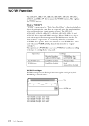
... a tape can be accidentally deleted or overwritten. When a WORM cartridge is being used with an application that supports the WORM function, data that data to be read from regular cartridges by their WORM logo and red shutters. Red WORM logo AIT-5 WORM cartridge: SDX5-400W AIT-4 WORM cartridge: SDX4-200W AIT-3 WORM cartridge: SDX3-100W AIT-2 WORM cartridge: SDX2-50W 28 Part 3. "WORM" is "WORM"? A WORM drive...
... a tape can be accidentally deleted or overwritten. When a WORM cartridge is being used with an application that supports the WORM function, data that data to be read from regular cartridges by their WORM logo and red shutters. Red WORM logo AIT-5 WORM cartridge: SDX5-400W AIT-4 WORM cartridge: SDX4-200W AIT-3 WORM cartridge: SDX3-100W AIT-2 WORM cartridge: SDX2-50W 28 Part 3. "WORM" is "WORM"? A WORM drive...

Operating Instructions
Page 32
... cartridge was carefully aligned during assembly at the factory. AIT-1 AIT-5 AIT-4 AIT-3 Ex AIT-3 AIT-2 Turbo AIT-2 AIT-1 Turbo AIT-E Turbo Using your fingernail, push the switch in the direction of the arrow). Do not open it or take it apart. • The write-protect switch on the face of a sudden change in a car. 32 Part 4. Care and Maintenance Return the switch to its original position to open the...
... cartridge was carefully aligned during assembly at the factory. AIT-1 AIT-5 AIT-4 AIT-3 Ex AIT-3 AIT-2 Turbo AIT-2 AIT-1 Turbo AIT-E Turbo Using your fingernail, push the switch in the direction of the arrow). Do not open it or take it apart. • The write-protect switch on the face of a sudden change in a car. 32 Part 4. Care and Maintenance Return the switch to its original position to open the...

Operating Instructions
Page 33
... AITe390V*, and the cartridge is automatically ejected when finished. * The cleaning time varies depending on the condition of the cartridge, dispose it . Care and Maintenance When the drive unit needs cleaning, the CLEANING REQUEST indicator lights. (For the AITe1040, AITe1040V, AITe520, AITe520V, AITe390, and AITe390V, use SDX5-CL AITe520, AITe520V SDX4-CL, SDX4-CLL AITe390, AITe390V SDX3X-CL AITe260, AITe260V, AITe130, AITe130V...
... AITe390V*, and the cartridge is automatically ejected when finished. * The cleaning time varies depending on the condition of the cartridge, dispose it . Care and Maintenance When the drive unit needs cleaning, the CLEANING REQUEST indicator lights. (For the AITe1040, AITe1040V, AITe520, AITe520V, AITe390, and AITe390V, use SDX5-CL AITe520, AITe520V SDX4-CL, SDX4-CLL AITe390, AITe390V SDX3X-CL AITe260, AITe260V, AITe130, AITe130V...

