Instruction Manual
Page 1
Instruction Manual and Parts List High Speed Straight Lockstitch Sewing Machine 191D 20/20C 30 / 30C 70 / 70C ® Singer is a registered trademark of The Singer Company Limited or its affiliated companies. © 2009 Copyright The Singer Company Limited
Instruction Manual and Parts List High Speed Straight Lockstitch Sewing Machine 191D 20/20C 30 / 30C 70 / 70C ® Singer is a registered trademark of The Singer Company Limited or its affiliated companies. © 2009 Copyright The Singer Company Limited

Instruction Manual
Page 4
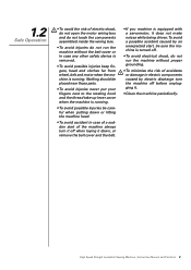
Safety Instructions 1.1 Important Safety Instructions Important When using the machine. Singer will not be followed. When using it as reference when necessary. • Before running the machine, make sure all instructions before using the machine, ...not be placed next to a sound source as an ultrasonic welding machine and other equipment. • The machine should only be run without its instructions manual, and indications of cold water. If any damage caused by properly trained personnel. • Maintenance and repair on electric equipment should be followed. In case...
Safety Instructions 1.1 Important Safety Instructions Important When using the machine. Singer will not be followed. When using it as reference when necessary. • Before running the machine, make sure all instructions before using the machine, ...not be placed next to a sound source as an ultrasonic welding machine and other equipment. • The machine should only be run without its instructions manual, and indications of cold water. If any damage caused by properly trained personnel. • Maintenance and repair on electric equipment should be followed. In case...
Instruction Manual
Page 5
... careful when putting down , or remove the belt cover and the belt. • If you machine is running. High Speed Straight Lockstitch Sewing Machine | Instruction Manual and Parts List 2 Nothing should be placed near those parts. • To avoid injuries never put your fingers next to the rotating hook and the...
... careful when putting down , or remove the belt cover and the belt. • If you machine is running. High Speed Straight Lockstitch Sewing Machine | Instruction Manual and Parts List 2 Nothing should be placed near those parts. • To avoid injuries never put your fingers next to the rotating hook and the...

Instruction Manual
Page 6
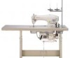
Product Description and Machine Specification 2.1 Product Description High Speed Straight Lockstitch Sewing Machine High Speed Straight Lockstitch Sewing Machine | Instruction Manual and Parts List 3
Product Description and Machine Specification 2.1 Product Description High Speed Straight Lockstitch Sewing Machine High Speed Straight Lockstitch Sewing Machine | Instruction Manual and Parts List 3

Instruction Manual
Page 7
... Straight Lockstitch Sewing Machine | Instruction Manual and Parts List 4 Lubrication Lubrication Oil 191D-20 Light to medium 191D-20C Standard 5,000 5.0 5.5/13.0 30.7 1955-01 #14 Koban/ Hirose Regular 191D-30 Medium to heavy 4,500 5.0 5.5/13.0 35.0 191D-30C Standard Koban/ Hirose 1955-01 #18 Fully Automatic Lubrication Singer "C" type oil 191D-70 Heavy 191D-70C Standard 3,000 7.0 5.5/13.0 35...
... Straight Lockstitch Sewing Machine | Instruction Manual and Parts List 4 Lubrication Lubrication Oil 191D-20 Light to medium 191D-20C Standard 5,000 5.0 5.5/13.0 30.7 1955-01 #14 Koban/ Hirose Regular 191D-30 Medium to heavy 4,500 5.0 5.5/13.0 35.0 191D-30C Standard Koban/ Hirose 1955-01 #18 Fully Automatic Lubrication Singer "C" type oil 191D-70 Heavy 191D-70C Standard 3,000 7.0 5.5/13.0 35...
Instruction Manual
Page 8
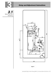
3.1 Table Cut-Out Drawing Setup and Adjustment Instructions + 1 181 - 0 115 22 130 2-R30 2-R22.5 50 2-R20 2-DEEP 17 2-80 2-R41-8R10 2-12.75 2-R20 4-R10 2-12.75 28 130 66 33 Ø8.5 339.7 2-DEEP 18 159 108 2-DEEP 23 28 DEEØP 1268 68.1 59 65 95 206 480 - 0 +1 1200 Ø18 DØE2E4P 1 4-R10 200 65 535 Figure 1 High Speed Straight Lockstitch Sewing Machine | Instruction Manual and Parts List 5
3.1 Table Cut-Out Drawing Setup and Adjustment Instructions + 1 181 - 0 115 22 130 2-R30 2-R22.5 50 2-R20 2-DEEP 17 2-80 2-R41-8R10 2-12.75 2-R20 4-R10 2-12.75 28 130 66 33 Ø8.5 339.7 2-DEEP 18 159 108 2-DEEP 23 28 DEEØP 1268 68.1 59 65 95 206 480 - 0 +1 1200 Ø18 DØE2E4P 1 4-R10 200 65 535 Figure 1 High Speed Straight Lockstitch Sewing Machine | Instruction Manual and Parts List 5

Instruction Manual
Page 9
... nail '2', and the other two rubber cushion '3' on the four corners of the machine table groove. Figure 4 Figure 5 High Speed Straight Lockstitch Sewing Machine | Instruction Manual and Parts List 6 3.2 Oil Reservoir Installation The oil reservoir should rest on the four corners of the table (Figures 4 and 5).
... nail '2', and the other two rubber cushion '3' on the four corners of the machine table groove. Figure 4 Figure 5 High Speed Straight Lockstitch Sewing Machine | Instruction Manual and Parts List 6 3.2 Oil Reservoir Installation The oil reservoir should rest on the four corners of the table (Figures 4 and 5).
Instruction Manual
Page 10
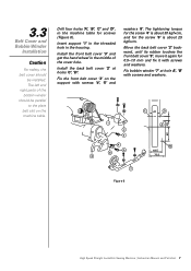
...hole A', 'B' with screws '4', '5' and washers '6'. The tightening torque for the screw '4' is about 25 kgf×cm. Figure 6 High Speed Straight Lockstitch Sewing Machine | Instruction Manual and Parts List 7 Insert support '1' in the threaded hole in the machine table for screws (Figure 6). Fix bobbin winder '7' at holes 'C', 'D'. Install the front belt...the machine table. Move the back belt cover '2' backward, until its rubber touches the front belt cover '3', move it again for the screw '5' is about 30 kgf×cm, and for 0.5~1.0 mm and fix it with screws and washers.
...hole A', 'B' with screws '4', '5' and washers '6'. The tightening torque for the screw '4' is about 25 kgf×cm. Figure 6 High Speed Straight Lockstitch Sewing Machine | Instruction Manual and Parts List 7 Insert support '1' in the threaded hole in the machine table for screws (Figure 6). Fix bobbin winder '7' at holes 'C', 'D'. Install the front belt...the machine table. Move the back belt cover '2' backward, until its rubber touches the front belt cover '3', move it again for the screw '5' is about 30 kgf×cm, and for 0.5~1.0 mm and fix it with screws and washers.

Instruction Manual
Page 11
... dot 'A' is brought close to 2,500 spm for about 10 minutes for the purpose of bread-in. Figure 8 High Speed Straight Lockstitch Sewing Machine | Instruction Manual and Parts List 8 The minimum amount of oil is reached when marker dot 'A' is brought to 'MAX' mark 'A' (Figure 7). 3.4 Lubrication Precaution When you will see...
... dot 'A' is brought close to 2,500 spm for about 10 minutes for the purpose of bread-in. Figure 8 High Speed Straight Lockstitch Sewing Machine | Instruction Manual and Parts List 8 The minimum amount of oil is reached when marker dot 'A' is brought to 'MAX' mark 'A' (Figure 7). 3.4 Lubrication Precaution When you will see...

Instruction Manual
Page 12
... increased, and toward '-' in direction 'B', the oil amount will be confirmed the state of oil supplied. Figure 11 High Speed Straight Lockstitch Sewing Machine | Instruction Manual and Parts List 9 The confirming time of the oil amount is 5 seconds (check the period of oil. Use the amount of oil confirmation paper for...
... increased, and toward '-' in direction 'B', the oil amount will be confirmed the state of oil supplied. Figure 11 High Speed Straight Lockstitch Sewing Machine | Instruction Manual and Parts List 9 The confirming time of the oil amount is 5 seconds (check the period of oil. Use the amount of oil confirmation paper for...
Instruction Manual
Page 13
... will go no further. Tighten the screw '2'. Make sure the long groove 'C' of sewing material used. Figure 12 High Speed Straight Lockstitch Sewing Machine | Instruction Manual and Parts List 10 Loosen screw '2' and hold needle '1' with its stroke (Figure 12). 3.7 Needle Attachment Caution Choose a proper needle size according to the count...
... will go no further. Tighten the screw '2'. Make sure the long groove 'C' of sewing material used. Figure 12 High Speed Straight Lockstitch Sewing Machine | Instruction Manual and Parts List 10 Loosen screw '2' and hold needle '1' with its stroke (Figure 12). 3.7 Needle Attachment Caution Choose a proper needle size according to the count...
Instruction Manual
Page 14
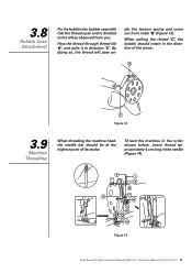
... bar should rotate in the needle (Figure 14). By doing so, the thread will pass un- Figure 14 High Speed Straight Lockstitch Sewing Machine | Instruction Manual and Parts List 11 3.8 Bobbin Case Attachment Fix the bobbin into bobbin case with that the thread open end is directed to the left as...
... bar should rotate in the needle (Figure 14). By doing so, the thread will pass un- Figure 14 High Speed Straight Lockstitch Sewing Machine | Instruction Manual and Parts List 11 3.8 Bobbin Case Attachment Fix the bobbin into bobbin case with that the thread open end is directed to the left as...
Instruction Manual
Page 15
... the tension of needle thread using tension adjusting nut '1' according to different sewing conditions. Figure 16 Figure 17 High Speed Straight Lockstitch Sewing Machine | Instruction Manual and Parts List 12 Turn the screw '2' counterclockwise (in direction 'D'), the bobbin thread tension will increase.
... the tension of needle thread using tension adjusting nut '1' according to different sewing conditions. Figure 16 Figure 17 High Speed Straight Lockstitch Sewing Machine | Instruction Manual and Parts List 12 Turn the screw '2' counterclockwise (in direction 'D'), the bobbin thread tension will increase.

Instruction Manual
Page 16
Figure 18 Figure 19 High Speed Straight Lockstitch Sewing Machine | Instruction Manual and Parts List 13 Turn the thread tension post '3' counter-clockwise (in direction 'A'), the pressure of the thread take-up spring will be increased. Adjusting ...
Figure 18 Figure 19 High Speed Straight Lockstitch Sewing Machine | Instruction Manual and Parts List 13 Turn the thread tension post '3' counter-clockwise (in direction 'A'), the pressure of the thread take-up spring will be increased. Adjusting ...

Instruction Manual
Page 17
... of the needle bar '2' in its original position when the lifter is 10 mm. Figure 22 Figure 23 High Speed Straight Lockstitch Sewing Machine | Instruction Manual and Parts List 14 The presser foot will go up to lift the presser foot (Figure 22). Figure 20 Figure 21 3.14 Presser Foot Lifter...
... of the needle bar '2' in its original position when the lifter is 10 mm. Figure 22 Figure 23 High Speed Straight Lockstitch Sewing Machine | Instruction Manual and Parts List 14 The presser foot will go up to lift the presser foot (Figure 22). Figure 20 Figure 21 3.14 Presser Foot Lifter...

Instruction Manual
Page 18
Turn the regulator '1' counter clockwise (in direction 'A'), the pressure of the presser foot will be decreased. Tighten nut '2'. For general sewing of the fabrics, the standard height of the presser spring regulator '1' will be increased (Figure 24). 3.15 Presser Foot Pressure Adjustment Loosen the nut '2', and turn the presser spring regulator '1' clockwise (in direction 'B'), the pressure of the presser foot will be around 33~36 mm (5 kg). ˜ 33 36mm Figure 24 High Speed Straight Lockstitch Sewing Machine | Instruction Manual and Parts List 15
Turn the regulator '1' counter clockwise (in direction 'A'), the pressure of the presser foot will be decreased. Tighten nut '2'. For general sewing of the fabrics, the standard height of the presser spring regulator '1' will be increased (Figure 24). 3.15 Presser Foot Pressure Adjustment Loosen the nut '2', and turn the presser spring regulator '1' clockwise (in direction 'B'), the pressure of the presser foot will be around 33~36 mm (5 kg). ˜ 33 36mm Figure 24 High Speed Straight Lockstitch Sewing Machine | Instruction Manual and Parts List 15

Instruction Manual
Page 19
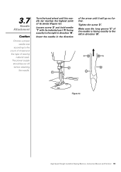
... to prevent uneven material feed, move the feed eccentric cam in the direction of the arrow. Figure 25 High Speed Straight Lockstitch Sewing Machine | Instruction Manual and Parts List 16 For the standard adjustment, adjust so that the top surface of feed dog and the top end of needle eyelet are...
... to prevent uneven material feed, move the feed eccentric cam in the direction of the arrow. Figure 25 High Speed Straight Lockstitch Sewing Machine | Instruction Manual and Parts List 16 For the standard adjustment, adjust so that the top surface of feed dog and the top end of needle eyelet are...

Instruction Manual
Page 20
Securely tighten screw '2'. Loosen screw '2' of the throat plate 'B' as the below for each machine variety (Figure 26). See description below height for height Figure 26 High Speed Straight Lockstitch Sewing Machine | Instruction Manual and Parts List 17 When the feed dog 'A' is tightening too much, the crank '1' will be above the top surface of crank '1'. Move the feed bar up or down to make a correct height. 3.17 Feed Dog Height Adjustment Caution If the screw '2' is at its highest position, the teeth should be worn out.
Securely tighten screw '2'. Loosen screw '2' of the throat plate 'B' as the below for each machine variety (Figure 26). See description below height for height Figure 26 High Speed Straight Lockstitch Sewing Machine | Instruction Manual and Parts List 17 When the feed dog 'A' is tightening too much, the crank '1' will be above the top surface of crank '1'. Move the feed bar up or down to make a correct height. 3.17 Feed Dog Height Adjustment Caution If the screw '2' is at its highest position, the teeth should be worn out.

Instruction Manual
Page 21
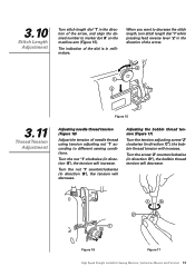
..., loosen the setscrew '1'. Adjusting the height of needle bar lower bushing '3', then securely tighten the setscrew '1'. Figure 27 High Speed Straight Lockstitch Sewing Machine | Instruction Manual and Parts List 18 3.18 Needle to Rotating Hook Relation Adjustment Precaution If the clearance is 0.04~0.1 mm. Adjusting the position of the rotating hook...
..., loosen the setscrew '1'. Adjusting the height of needle bar lower bushing '3', then securely tighten the setscrew '1'. Figure 27 High Speed Straight Lockstitch Sewing Machine | Instruction Manual and Parts List 18 3.18 Needle to Rotating Hook Relation Adjustment Precaution If the clearance is 0.04~0.1 mm. Adjusting the position of the rotating hook...

Instruction Manual
Page 22
Tighten the setscrew '1' after adjustment. When the presser foot rises to the highest, the distance between the throat plate and the presser foot is 5.5 mm (Figure 29). Figure 28 5,5mm Figure 29 High Speed Straight Lockstitch Sewing Machine | Instruction Manual and Parts List 19 3.19 Presser Bar Height Adjustment Loosen setscrew '1' (Figure 28) and adjust the height of the presser bar.
Tighten the setscrew '1' after adjustment. When the presser foot rises to the highest, the distance between the throat plate and the presser foot is 5.5 mm (Figure 29). Figure 28 5,5mm Figure 29 High Speed Straight Lockstitch Sewing Machine | Instruction Manual and Parts List 19 3.19 Presser Bar Height Adjustment Loosen setscrew '1' (Figure 28) and adjust the height of the presser bar.


