
Service Manual
Page 1
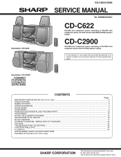
... PACKING OF THE SET (For U.S.A. The contents are subject to those specified be used . Only) SHARP CORP- Illustration: CD-C622 Illustration: CD-C2900 CD-C622/C2900 SERVICE MANUAL No. CONTENTS Page IMPORTANT SERVICE NOTES (For U.S.A. S3908CDC622// CD-C622 CD-C622 mini component system consisting of user-safety the set should be restored to its original condition and only parts...
... PACKING OF THE SET (For U.S.A. The contents are subject to those specified be used . Only) SHARP CORP- Illustration: CD-C622 Illustration: CD-C2900 CD-C622/C2900 SERVICE MANUAL No. CONTENTS Page IMPORTANT SERVICE NOTES (For U.S.A. S3908CDC622// CD-C622 CD-C622 mini component system consisting of user-safety the set should be restored to its original condition and only parts...
Service Manual
Page 2
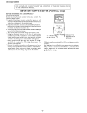
... not pinched or that no shock hazard exists, check for leakage current in the following safety checks. 1. Inspect all lead dress to the owner. - 2 - CD-C622/C2900 FOR A COMPLETE DESCRIPTION OF THE OPERATION OF THIS UNIT, PLEASE REFER TO THE OPERATION MANUAL. Only) BEFORE RETURNING THE AUDIO PRODUCT (Fire & Shock Hazard) Before...
... not pinched or that no shock hazard exists, check for leakage current in the following safety checks. 1. Inspect all lead dress to the owner. - 2 - CD-C622/C2900 FOR A COMPLETE DESCRIPTION OF THE OPERATION OF THIS UNIT, PLEASE REFER TO THE OPERATION MANUAL. Only) BEFORE RETURNING THE AUDIO PRODUCT (Fire & Shock Hazard) Before...
Service Manual
Page 3
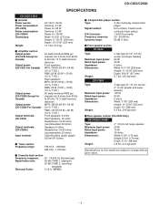
... Width; 6-3/4" (170 mm) Height; 6-3/4" (170 mm) Depth; 3-1/2" (88 mm) 0.9 lbs. (0.4 kg)/each Specifications for Canada) Output power: (CD-C2900 For Canada) Output terminals: (CD-C622) Output terminals: (CD-C2900) Input terminal: 40 watts minimum RMS per channel into 4 ohms from 60 Hz to 20 kHz, 10 % total harmonic distortion MPO; 180...000 Hz (Normal tape) Signal/noise ratio: 55 dB (TAPE 1, playback) 50 dB (TAPE 2, recording/ playback) Wow and flutter: 0.15 % (WRMS) Compact disc player section Type: 3-disc multi-play compact disc player Signal readout: Non-contact, 3-beam semi-
... Width; 6-3/4" (170 mm) Height; 6-3/4" (170 mm) Depth; 3-1/2" (88 mm) 0.9 lbs. (0.4 kg)/each Specifications for Canada) Output power: (CD-C2900 For Canada) Output terminals: (CD-C622) Output terminals: (CD-C2900) Input terminal: 40 watts minimum RMS per channel into 4 ohms from 60 Hz to 20 kHz, 10 % total harmonic distortion MPO; 180...000 Hz (Normal tape) Signal/noise ratio: 55 dB (TAPE 1, playback) 50 dB (TAPE 2, recording/ playback) Wow and flutter: 0.15 % (WRMS) Compact disc player section Type: 3-disc multi-play compact disc player Signal readout: Non-contact, 3-beam semi-

Service Manual
Page 4
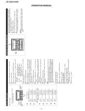
... Indicator 8. Timer Indicator 17. Power Button 25. Headphones Socket 29. Function Selector Buttons 30. CD-C622/C2900 CD-C622/C2900 Front Panel 1. Disc Skip Button 5. FM Stereo Indicator 9. (CD) Repeat Indicator 10. (CD) Play Indicator 11. (CD) Pause Indicator 12. Clock Button 23. Volume Up/Down Buttons 6 9 7 10 8 11 12 13 14 15 16 17 18 19 20...
... Indicator 8. Timer Indicator 17. Power Button 25. Headphones Socket 29. Function Selector Buttons 30. CD-C622/C2900 CD-C622/C2900 Front Panel 1. Disc Skip Button 5. FM Stereo Indicator 9. (CD) Repeat Indicator 10. (CD) Play Indicator 11. (CD) Pause Indicator 12. Clock Button 23. Volume Up/Down Buttons 6 9 7 10 8 11 12 13 14 15 16 17 18 19 20...

Service Manual
Page 5
...Repeat Button 10. Stop Button 11. Function Selector Buttons 21. Woofer 3. Speaker Wire CP-C2900 1. Remote Control Transmitter LED CD Control section 2. Pause Button 5. Equalizer Mode Selector Button 20. Extra Bass Button 23. Volume Up/Down Buttons CD-C622/C2900 1 2 4 3 1 2 3 4 5 1 2 1 2 8 3 9... Memory Button 4. Random Button Tuner control section 12. Bass Reflex Ducts 4. Power Button 22. Full Range Speaker 2. Speaker Wire CD-C622/C2900 Remote Control 1. Tweeter 3. Woofer 4. Track Up/Cue Button 8. Preset Up/Down Buttons: Tape control section 13. (TAPE 1)...
...Repeat Button 10. Stop Button 11. Function Selector Buttons 21. Woofer 3. Speaker Wire CP-C2900 1. Remote Control Transmitter LED CD Control section 2. Pause Button 5. Equalizer Mode Selector Button 20. Extra Bass Button 23. Volume Up/Down Buttons CD-C622/C2900 1 2 4 3 1 2 3 4 5 1 2 1 2 8 3 9... Memory Button 4. Random Button Tuner control section 12. Bass Reflex Ducts 4. Power Button 22. Full Range Speaker 2. Speaker Wire CD-C622/C2900 Remote Control 1. Tweeter 3. Woofer 4. Track Up/Cue Button 8. Preset Up/Down Buttons: Tape control section 13. (TAPE 1)...
Service Manual
Page 6
...8594; The 12-hour display will appear. (AM 0:00 - OPERATION MANUAL CD-C622/C2900 SETTING THE CLOCK (Main unit operation) In this happens, follow the procedure ... that this can only be set when the unit is set for the 12-hour (AM 12:00) system. If the display is selected, "AM" will not advance even if minutes advance from "0" seconds. (...displayed.) Note: In the event of the stored memory contents (clock and timer settings, and tuner and CD presets). ton, hold down the button and the but- RESETTING THE MICROCOMPUTER 2 1,2 Reset the microcomputer under...
...8594; The 12-hour display will appear. (AM 0:00 - OPERATION MANUAL CD-C622/C2900 SETTING THE CLOCK (Main unit operation) In this happens, follow the procedure ... that this can only be set when the unit is set for the 12-hour (AM 12:00) system. If the display is selected, "AM" will not advance even if minutes advance from "0" seconds. (...displayed.) Note: In the event of the stored memory contents (clock and timer settings, and tuner and CD presets). ton, hold down the button and the but- RESETTING THE MICROCOMPUTER 2 1,2 Reset the microcomputer under...

Service Manual
Page 9
...-4 (Note 2) 2. Open the cassette holder. 10-2 2. Screw K1) x1 10-3 2. CD-C622/C2900 DISASSEMBLY Caution on Disassembly Follow the below-mentioned notes when disassembling (Illustration: CD-C622) CD-C622/C2900 the unit and reassembling it safe and ensure excellent performance: 1. Change, turn fully the lock ...the wall (A1)x2 ø3x12mm outlet before disassembling. (B2)x1 4. Take cassette tape and compact disc out of integrated circuits and other circuits when servicing. (B1)x1 ø3x8mm Top Cabinet CD-C622/C2900 STEP REMOVAL PROCEDURE FIGURE 1 Top Cabinet 1.
...-4 (Note 2) 2. Open the cassette holder. 10-2 2. Screw K1) x1 10-3 2. CD-C622/C2900 DISASSEMBLY Caution on Disassembly Follow the below-mentioned notes when disassembling (Illustration: CD-C622) CD-C622/C2900 the unit and reassembling it safe and ensure excellent performance: 1. Change, turn fully the lock ...the wall (A1)x2 ø3x12mm outlet before disassembling. (B2)x1 4. Take cassette tape and compact disc out of integrated circuits and other circuits when servicing. (B1)x1 ø3x8mm Top Cabinet CD-C622/C2900 STEP REMOVAL PROCEDURE FIGURE 1 Top Cabinet 1.

Service Manual
Page 10
CD-C622/C2900 (E2)x2 (E3)x1 (E5)x1 (E2)x2 (G1)x1 (E4)x1 (E1)x1 ø3x10mm Front Panel ( M2 ) x2 ( M1 ) x1 ø3 x10mm CD Servo PWB (E1)x2 ø3x8mm Main PWB (F1)x1 ø3x8mm Switch PWB Figure 10-1 (G1)x1 Front Panel (G2)x2 ø3x10mm (G2... Unit Figure 10-4 ( P1 ) x1 ø2.6 x10mm ( N1 ) x4 ø3 x12mm Shift Lever CD Changer Mechanism CD Player Base CD Mechanism Care when installing the CD changer mechanism. Install the CD changer mechanism on the CD player base after the shift lever has been set in the highest position. Figure 10-5 ( L1 ) x1 ø3 x10mm...
CD-C622/C2900 (E2)x2 (E3)x1 (E5)x1 (E2)x2 (G1)x1 (E4)x1 (E1)x1 ø3x10mm Front Panel ( M2 ) x2 ( M1 ) x1 ø3 x10mm CD Servo PWB (E1)x2 ø3x8mm Main PWB (F1)x1 ø3x8mm Switch PWB Figure 10-1 (G1)x1 Front Panel (G2)x2 ø3x10mm (G2... Unit Figure 10-4 ( P1 ) x1 ø2.6 x10mm ( N1 ) x4 ø3 x12mm Shift Lever CD Changer Mechanism CD Player Base CD Mechanism Care when installing the CD changer mechanism. Install the CD changer mechanism on the CD player base after the shift lever has been set in the highest position. Figure 10-5 ( L1 ) x1 ø3 x10mm...

Service Manual
Page 11
Therefore the disassembling method is not discribed. Screw A3) x2 4. Screw A5) x4 11-2 CP-C2900 Front Panel (A1)x1 Super Tweeter Tweeter (A3)x2 ø3x10mm (A2)x2 (A4)x2 ø3x10mm (A5)x4 ø4x14mm Figure 11-2 Screw Driver ...Woofer Screw Driver - 11 - For details refer to the disassembling drawing in the Parts Guide. CD-C622/C2900 CP-C622 Front Panel (A1)x1 Piezo (A3)x4 (A2)x2 ø4x12mm Woofer Figure 11-1 CP-C2900 STEP REMOVAL 1 Front Speaker PROCEDURE FIGURE 1. CP-C622 STEP REMOVAL PROCEDURE FIGURE 1 Front Speaker 1. Screw A4...
Therefore the disassembling method is not discribed. Screw A3) x2 4. Screw A5) x4 11-2 CP-C2900 Front Panel (A1)x1 Super Tweeter Tweeter (A3)x2 ø3x10mm (A2)x2 (A4)x2 ø3x10mm (A5)x4 ø4x14mm Figure 11-2 Screw Driver ...Woofer Screw Driver - 11 - For details refer to the disassembling drawing in the Parts Guide. CD-C622/C2900 CP-C622 Front Panel (A1)x1 Piezo (A3)x4 (A2)x2 ø4x12mm Woofer Figure 11-1 CP-C2900 STEP REMOVAL 1 Front Speaker PROCEDURE FIGURE 1. CP-C622 STEP REMOVAL PROCEDURE FIGURE 1 Front Speaker 1. Screw A4...

Service Manual
Page 12
... conductive aluminium foil around the front end of the disassembly method to remove the CD mechanism. Remove the stop washer (B3) x 1 pc., to remove the gear (B4). 3. Remove the pickup. CD-C622/C2900 REMOVING AND REINSTALLING THE MAIN PARTS CD MECHANISM SECTION Perform steps 1, 2, 3, 13 and 14 of connector so as to protect the...
... conductive aluminium foil around the front end of the disassembly method to remove the CD mechanism. Remove the stop washer (B3) x 1 pc., to remove the gear (B4). 3. Remove the pickup. CD-C622/C2900 REMOVING AND REINSTALLING THE MAIN PARTS CD MECHANISM SECTION Perform steps 1, 2, 3, 13 and 14 of connector so as to protect the...
Service Manual
Page 13
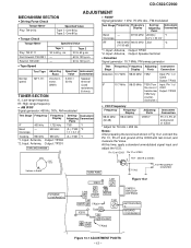
... 76 kHz ± 200 Hz. Tape 2 30 to 60 g.cm 60 to 120 g.cm 60 to 60 g. Coverage 530 kHz Tracking 990 kHz 990 kHz *1. CD-C622/C2900 ADJUSTMENT MECHANISM SECTION • Driving Force Check Torque Meter Specified Value Play: TW-2412 Tape 1: Over 80 g Tape 2: Over 80 g • Torque Check Torque...
... 76 kHz ± 200 Hz. Tape 2 30 to 60 g.cm 60 to 120 g.cm 60 to 60 g. Coverage 530 kHz Tracking 990 kHz 990 kHz *1. CD-C622/C2900 ADJUSTMENT MECHANISM SECTION • Driving Force Check Torque Meter Specified Value Play: TW-2412 Tape 1: Over 80 g Tape 2: Over 80 g • Torque Check Torque...
Service Manual
Page 14
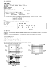
...Indication of PWB and laser pickup unit is manual operation. LASER ON Tracking on the spot. CENTER R.GEQ. --- POWER OFF Press key. Since this CD system incorporates the following key is pressed during PLAY, it is possible to readjust it. E/F balance (tracking error balance) (Fig. 14-4) 4. SERVO ...is possible to slide the pickup with the ( ) or ( ) key. SERVO OFF PLAY Tracking on the spot. IL is performed. VOL. --- CD-C622/C2900 TEST MODE • Setting the test mode Any one of test mode can be set by using the optimal settings. 0.1s 0.50 V IC1 20 FE...
...Indication of PWB and laser pickup unit is manual operation. LASER ON Tracking on the spot. CENTER R.GEQ. --- POWER OFF Press key. Since this CD system incorporates the following key is pressed during PLAY, it is possible to readjust it. E/F balance (tracking error balance) (Fig. 14-4) 4. SERVO ...is possible to slide the pickup with the ( ) or ( ) key. SERVO OFF PLAY Tracking on the spot. IL is performed. VOL. --- CD-C622/C2900 TEST MODE • Setting the test mode Any one of test mode can be set by using the optimal settings. 0.1s 0.50 V IC1 20 FE...

Service Manual
Page 15
... this model are important for maintaining the safety and performance of the set . REF. In the tuner section, ( ) indicates AM < > indicates FM stereo 2. In the deck section, a tape is being played back. 5. NO SW1 SW2 SW3 SW4 SW701 SW703 SW704 SW705 SW706 SW707 SW708 SW709 SW710 SW711 ...in each section is the one with specified ones for maintaining the safety of the set . In the CD section, the CD is stopped. • Parts marked with no signal given. 1. CD-C622/C2900 NOTES ON SCHEMATIC DIAGRAM • Resistor: To differentiate the units of resistors, such symbol as K and...
... this model are important for maintaining the safety and performance of the set . REF. In the tuner section, ( ) indicates AM < > indicates FM stereo 2. In the deck section, a tape is being played back. 5. NO SW1 SW2 SW3 SW4 SW701 SW703 SW704 SW705 SW706 SW707 SW708 SW709 SW710 SW711 ...in each section is the one with specified ones for maintaining the safety of the set . In the CD section, the CD is stopped. • Parts marked with no signal given. 1. CD-C622/C2900 NOTES ON SCHEMATIC DIAGRAM • Resistor: To differentiate the units of resistors, such symbol as K and...

Service Manual
Page 16
CD-C622/C2900 1 5ms 0.50 V IC1 20 F.E 2 5ms 5.0 V IC1 54 DRF 3 0.5ms 1.00 V HF 4 0.5ms 5.0 V HFL 5 0.5ms 5.0 V TES 3 0.5ms 1.00 V HF 4 0.5ms 5.0 V HFL 5 0.5ms 5.0 V TES 6 50ms 10.0 V JP+ 7 ... 10.0 V JP+ 7 0.5ms 10.0 V JP- 8 0.5ms 0.50 V JP 9 0.5ms 1.00 V TE 6 50ms 10.0 V JP+ 7 50ms 10.0 V JP- 8 50ms 0.50 V JP 9 50ms 1.00 V TE WAVEFORMS OF CD CIRCUIT STOP FOCUS PLAY SERCH 3 1 6 0.5ms 10.0 V JP+ 7 0.5ms 10.0 V JP- 8 0.5ms 0.50 V JP 9 0.5ms 1.00 V TE CUE 1 2 3 10 20ms 1.00 V SPO 11 20ms 2.00...
CD-C622/C2900 1 5ms 0.50 V IC1 20 F.E 2 5ms 5.0 V IC1 54 DRF 3 0.5ms 1.00 V HF 4 0.5ms 5.0 V HFL 5 0.5ms 5.0 V TES 3 0.5ms 1.00 V HF 4 0.5ms 5.0 V HFL 5 0.5ms 5.0 V TES 6 50ms 10.0 V JP+ 7 ... 10.0 V JP+ 7 0.5ms 10.0 V JP- 8 0.5ms 0.50 V JP 9 0.5ms 1.00 V TE 6 50ms 10.0 V JP+ 7 50ms 10.0 V JP- 8 50ms 0.50 V JP 9 50ms 1.00 V TE WAVEFORMS OF CD CIRCUIT STOP FOCUS PLAY SERCH 3 1 6 0.5ms 10.0 V JP+ 7 0.5ms 10.0 V JP- 8 0.5ms 0.50 V JP 9 0.5ms 1.00 V TE CUE 1 2 3 10 20ms 1.00 V SPO 11 20ms 2.00...

Service Manual
Page 17
CD-C622/C2900 Figure 17 BLOCK DIAGRAM (1/3) - 17 - PICKUP UNIT FOCUS COIL TRACKING COIL M2 SLED MOTOR M M1 SPINDLE MOTOR M PICKUP IN SW4 TO FD SPO NC SLD ...
CD-C622/C2900 Figure 17 BLOCK DIAGRAM (1/3) - 17 - PICKUP UNIT FOCUS COIL TRACKING COIL M2 SLED MOTOR M M1 SPINDLE MOTOR M PICKUP IN SW4 TO FD SPO NC SLD ...

Service Manual
Page 18
...ST MPX IN 16 L 9 R 10 FM/AM 11 Q350 AM OSC IN AM+B AM RF IN STEREO AM TRACKING T331 AM BAND COVERAGE T333 Q343 FM/AM SWITCHING +B7 1 IC704 3 2 AM IN FM ...OSC 15 16 IC302 11 3 4 5 6 VOLTAGE REGURATER LC72131 17 +B4 PLL (TUNER) 7 10 21 FM SWITCHING FROM CD SECTION CNP11 CNS11 1 2 3 TAPE 1 PB HEAD L-CH R-CH TAPE 2 L-CH R-CH REC PB HEAD REC P.B SWITCHING... BIAS OCS Q128 L104 SWITCHING Q124 L103 BAIS Q126 T1/T2 BAIS Figure 18 BLOCK DIAGRAM (2/3) - 18 - CD-C622/C2900 FM AM LOOP ANTENNA ANTENNA L301 FM B.P.F IC301 1 TA7358AP 6 FM FRONT END 9 23 4 5 7 ...
...ST MPX IN 16 L 9 R 10 FM/AM 11 Q350 AM OSC IN AM+B AM RF IN STEREO AM TRACKING T331 AM BAND COVERAGE T333 Q343 FM/AM SWITCHING +B7 1 IC704 3 2 AM IN FM ...OSC 15 16 IC302 11 3 4 5 6 VOLTAGE REGURATER LC72131 17 +B4 PLL (TUNER) 7 10 21 FM SWITCHING FROM CD SECTION CNP11 CNS11 1 2 3 TAPE 1 PB HEAD L-CH R-CH TAPE 2 L-CH R-CH REC PB HEAD REC P.B SWITCHING... BIAS OCS Q128 L104 SWITCHING Q124 L103 BAIS Q126 T1/T2 BAIS Figure 18 BLOCK DIAGRAM (2/3) - 18 - CD-C622/C2900 FM AM LOOP ANTENNA ANTENNA L301 FM B.P.F IC301 1 TA7358AP 6 FM FRONT END 9 23 4 5 7 ...

Service Manual
Page 19
CD-C622/C2900 SWM3 PROOF SWM4 F.A.S SOLM1 ENOID SWM5 CAM R351 VCO ADJ MONO/ST 3 15 CO MO/ST L 9 R 10 N FM/AM 11 Q343 AM ... 81 49 82 48 83 47 84 46 VDD 85 45 86 44 87 43 IC701 88 42 IX0280AW 89 41 40 SYSTEM CONTROL 90 91 39 MICROCOMPUTER 92 38 93 37 94 36 95 35 96 34 AVDD 97 33 98 VDD 32 99... 14 13 12 11 10 9 8 7 6 5 4 3 2 1 UNSWITCH +B7 MEMORY BACK UP KEY SW701 ~SW730 +B5 PHM1 +B7 XL701 Q704 4.19MHz TO CD SECTION Q960 +B1 M M901 FAN MOTOR +B5 -B4 13 R P 8 L ESSOR Q121 Q122 UTING REC T1/T2 Q601 Q603 Q602 Q604 +B1 +7.3V Q908 RL901...
CD-C622/C2900 SWM3 PROOF SWM4 F.A.S SOLM1 ENOID SWM5 CAM R351 VCO ADJ MONO/ST 3 15 CO MO/ST L 9 R 10 N FM/AM 11 Q343 AM ... 81 49 82 48 83 47 84 46 VDD 85 45 86 44 87 43 IC701 88 42 IX0280AW 89 41 40 SYSTEM CONTROL 90 91 39 MICROCOMPUTER 92 38 93 37 94 36 95 35 96 34 AVDD 97 33 98 VDD 32 99... 14 13 12 11 10 9 8 7 6 5 4 3 2 1 UNSWITCH +B7 MEMORY BACK UP KEY SW701 ~SW730 +B5 PHM1 +B7 XL701 Q704 4.19MHz TO CD SECTION Q960 +B1 M M901 FAN MOTOR +B5 -B4 13 R P 8 L ESSOR Q121 Q122 UTING REC T1/T2 Q601 Q603 Q602 Q604 +B1 +7.3V Q908 RL901...

Service Manual
Page 32
CD-C622/C2900 CD-C2900 R609 A AM LOOP ANTENNA B 3 2 1 FM ANTENNA C M901 FAN MOTOR R-CH JK601 D VIDEO IN L-CH CNS804 RD 2 1 BR E F L-CH + R-CH + SO901 FRONT SPEAKER 6 OHMS TERMINAL MIN. G H ...
CD-C622/C2900 CD-C2900 R609 A AM LOOP ANTENNA B 3 2 1 FM ANTENNA C M901 FAN MOTOR R-CH JK601 D VIDEO IN L-CH CNS804 RD 2 1 BR E F L-CH + R-CH + SO901 FRONT SPEAKER 6 OHMS TERMINAL MIN. G H ...

Service Manual
Page 36
A TO TAPE MECHANISM PWB 1 2 3 4 5 6 Figure 36 WIRING SIDE OF P.W.BOARD (7/11) - 36 - B TO CD SERVO PWB P38 6 - C718 RS712 C719 IC703 RS711 CD-C622/C2900 CD-C2900 A SWITCH PWB-A4 RS707 10 9 LED707 RS706 LED706 SW709 RD09 OPEN/CLOSE SW708 DISC SKIP 18 1 RS705 B DISPLAY PWB-A3 COLOR TABLE LED705 RS704 LED704 ...
A TO TAPE MECHANISM PWB 1 2 3 4 5 6 Figure 36 WIRING SIDE OF P.W.BOARD (7/11) - 36 - B TO CD SERVO PWB P38 6 - C718 RS712 C719 IC703 RS711 CD-C622/C2900 CD-C2900 A SWITCH PWB-A4 RS707 10 9 LED707 RS706 LED706 SW709 RD09 OPEN/CLOSE SW708 DISC SKIP 18 1 RS705 B DISPLAY PWB-A3 COLOR TABLE LED705 RS704 LED704 ...
Service Manual
Page 55
..."D" ±0.5%.) If there are ±5% carbon-film type. "HOW TO ORDER REPLACEMENT PARTS" To have your nearest SHARP Parts Distributor to replace parts with " " are important for maintaining the safety and performance of capacitors/resistors parts codes ...lead wire) VR J .. CD-C2900 CD-C2900 mini component system consisting of CD-C622 mini component system, CP-C622 and rear (GBOXS0021AWM1) speaker system. PARTS GUIDE CD-C622/C2900 MODEL CD-C622 CD-C622 mini component system consisting of CD-C2900 mini component system and CP-C2900 speaker system. NOTE: Parts marked with...
..."D" ±0.5%.) If there are ±5% carbon-film type. "HOW TO ORDER REPLACEMENT PARTS" To have your nearest SHARP Parts Distributor to replace parts with " " are important for maintaining the safety and performance of capacitors/resistors parts codes ...lead wire) VR J .. CD-C2900 CD-C2900 mini component system consisting of CD-C622 mini component system, CP-C622 and rear (GBOXS0021AWM1) speaker system. PARTS GUIDE CD-C622/C2900 MODEL CD-C622 CD-C622 mini component system consisting of CD-C2900 mini component system and CP-C2900 speaker system. NOTE: Parts marked with...


