
Service Manual
Page 2
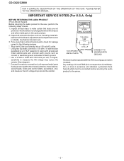
... AC outlet. * Using two clip leads, connect a 1.5k ohm, 10 watt resistor paralleled by a 0.15µF capacitor in the following safety checks. 1. Inspect all protective devices such as conduit or electrical ground connected to earth ground. * Use a VTVM or VOM with all lead dress to the owner. - 2 - Inspect all exposed... compartment covers or shields, mechanical insulators etc. 3. AC.) or more is not lodged between the chassis and other metal parts in the audio product. 2. CD-C622/C2900 FOR A COMPLETE DESCRIPTION OF THE OPERATION OF THIS UNIT, PLEASE REFER TO THE OPERATION MANUAL.
... AC outlet. * Using two clip leads, connect a 1.5k ohm, 10 watt resistor paralleled by a 0.15µF capacitor in the following safety checks. 1. Inspect all protective devices such as conduit or electrical ground connected to earth ground. * Use a VTVM or VOM with all lead dress to the owner. - 2 - Inspect all exposed... compartment covers or shields, mechanical insulators etc. 3. AC.) or more is not lodged between the chassis and other metal parts in the audio product. 2. CD-C622/C2900 FOR A COMPLETE DESCRIPTION OF THE OPERATION OF THIS UNIT, PLEASE REFER TO THE OPERATION MANUAL.

Service Manual
Page 9
Take cassette tape and compact disc out of integrated circuits and other circuits when servicing. (B1)x1 ø3x8mm Top Cabinet CD-C622/C2900 STEP REMOVAL PROCEDURE FIGURE 1 Top Cabinet 1. Take suffcient care on the loading chassis bottom in this state. Screw B1) x6 9-1 2. Hook C1) ... as to disassemble the unit. 3. Screw M1) x1 10-4 (Note 2) 2. Take off nylon bands or wire holders where they were before starting to protect the optical pickup from the wall (A1)x2 ø3x12mm outlet before disassembling. (B2)x1 4. Socket C3) x3 4 Back Board (with Digital Output ...
Take cassette tape and compact disc out of integrated circuits and other circuits when servicing. (B1)x1 ø3x8mm Top Cabinet CD-C622/C2900 STEP REMOVAL PROCEDURE FIGURE 1 Top Cabinet 1. Take suffcient care on the loading chassis bottom in this state. Screw B1) x6 9-1 2. Hook C1) ... as to disassemble the unit. 3. Screw M1) x1 10-4 (Note 2) 2. Take off nylon bands or wire holders where they were before starting to protect the optical pickup from the wall (A1)x2 ø3x12mm outlet before disassembling. (B2)x1 4. Socket C3) x3 4 Back Board (with Digital Output ...

Service Manual
Page 12
...., to remove the shaft (B2). 2. Remove the screws (B1) x 2 pcs., to remove the gear (B4). 3. CD-C622/C2900 REMOVING AND REINSTALLING THE MAIN PARTS CD MECHANISM SECTION Perform steps 1, 2, 3, 13 and 14 of connector so as to protect the optical pickup from electrostatic damage. ( B1 ) x2 Stop Washer ø2.6 x6mm ( B3 ) x1 Pickup Shaft...
...., to remove the shaft (B2). 2. Remove the screws (B1) x 2 pcs., to remove the gear (B4). 3. CD-C622/C2900 REMOVING AND REINSTALLING THE MAIN PARTS CD MECHANISM SECTION Perform steps 1, 2, 3, 13 and 14 of connector so as to protect the optical pickup from electrostatic damage. ( B1 ) x2 Stop Washer ø2.6 x6mm ( B3 ) x1 Pickup Shaft...


