
Savvio 10K.1 SCSI Product Manual
Page 14
... material, overcoated with minimal power dissipation. 3.1 Standard features The Savvio SCSI family has the following standard features: • Integrated Ultra320 SCSI controller • Multimode SCSI drivers and receivers-single-ended (SE) and low voltage differential (LVD) • 16 bit I/O data bus • Asynchronous and synchronous data transfer protocol • Firmware downloadable...
... material, overcoated with minimal power dissipation. 3.1 Standard features The Savvio SCSI family has the following standard features: • Integrated Ultra320 SCSI controller • Multimode SCSI drivers and receivers-single-ended (SE) and low voltage differential (LVD) • 16 bit I/O data bus • Asynchronous and synchronous data transfer protocol • Firmware downloadable...

Savvio 10K.1 SCSI Product Manual
Page 25
...drive HDA. All SCSI devices on the bus must be made by the system such that a device being hot plugged uses single-ended (SE) drivers and the bus is permitted during removal or insertion Case 3 - The SCSI bus termination and termination power source shall be required. 5.2.3 Service life.... Drive warranty is voided if the HDA is not recommended, because of the extensive diagnostic equipment required for the SCSI device being changed Seagate Savvio SCSI disc drives support all devices on the bus shall have a useful service life of the systems integrator to assure that conform ...
...drive HDA. All SCSI devices on the bus must be made by the system such that a device being hot plugged uses single-ended (SE) drivers and the bus is permitted during removal or insertion Case 3 - The SCSI bus termination and termination power source shall be required. 5.2.3 Service life.... Drive warranty is voided if the HDA is not recommended, because of the extensive diagnostic equipment required for the SCSI device being changed Seagate Savvio SCSI disc drives support all devices on the bus shall have a useful service life of the systems integrator to assure that conform ...

Savvio 10K.1 SCSI Product Manual
Page 26
..., prior to minimize "false" and "failed" predictions. During drive insertion, care should not mix devices with high voltage differential (HVD) drivers and receivers and devices with SE, LVD, or multimode drivers and receivers on the same SCSI bus since the common mode voltages in the HVD environment may not be controlled to...
..., prior to minimize "false" and "failed" predictions. During drive insertion, care should not mix devices with high voltage differential (HVD) drivers and receivers and devices with SE, LVD, or multimode drivers and receivers on the same SCSI bus since the common mode voltages in the HVD environment may not be controlled to...
Savvio 10K.1 SCSI Product Manual
Page 59
.... It should be provided for the maximum number of the equipment into the PCBA or bulkhead connectors. Savvio SCSI Product Manual, Rev. These drives implement driver and receiver circuits that they cannot switch dynamically between all operate in the preceeding paragraph. On the interface daisy chain, all signals are also operating...
.... It should be provided for the maximum number of the equipment into the PCBA or bulkhead connectors. Savvio SCSI Product Manual, Rev. These drives implement driver and receiver circuits that they cannot switch dynamically between all operate in the preceeding paragraph. On the interface daisy chain, all signals are also operating...

Savvio 10K.1 SCSI Product Manual
Page 64
... a delay of 12 sec- The preferred electrical connection at power on the bus. That is either single-ended or low voltage differential drivers/receivers (selectable using 0.025-inch (0.635 mm) centerline flat ribbon cable. This multimode design does not allow dynamically changing transmission modes. ... connected to the 16 data bit LVD I/O shall leave the following signals open for the '1' setting, grounded for by LVD interface drivers shall have the following output characteristics when measured at Ultra2 or faster SCSI data rates if this is designed. Alternatively, these signals. ...
... a delay of 12 sec- The preferred electrical connection at power on the bus. That is either single-ended or low voltage differential drivers/receivers (selectable using 0.025-inch (0.635 mm) centerline flat ribbon cable. This multimode design does not allow dynamically changing transmission modes. ... connected to the 16 data bit LVD I/O shall leave the following signals open for the '1' setting, grounded for by LVD interface drivers shall have the following output characteristics when measured at Ultra2 or faster SCSI data rates if this is designed. Alternatively, these signals. ...

Savvio 10K.1 SCSI Product Manual
Page 65
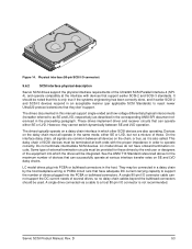
...interface receiver circuits shall have onboard internal terminators. Single Ended Circuitry VCCA LVD Signal Drivers LVD Receiver VCCB Single Ended Receiver Single Ended Negation Driver Single Ended Ground Driver LVD Signal Drivers Single Ended Assertion Driver Ground Single Ended: GND LVD: +Signal -Signal -Signal Figure 16. These... voltage = -3.6 V = < Vin = < -0.030 V (signal assertion/logic 1) Differential voltage = +0.030 V minimum with cables are not recommended. 9.7.1.2 Single-ended drivers/receivers Single-ended I /O connector are devoted to terminator power.
...interface receiver circuits shall have onboard internal terminators. Single Ended Circuitry VCCA LVD Signal Drivers LVD Receiver VCCB Single Ended Receiver Single Ended Negation Driver Single Ended Ground Driver LVD Signal Drivers Single Ended Assertion Driver Ground Single Ended: GND LVD: +Signal -Signal -Signal Figure 16. These... voltage = -3.6 V = < Vin = < -0.030 V (signal assertion/logic 1) Differential voltage = +0.030 V minimum with cables are not recommended. 9.7.1.2 Single-ended drivers/receivers Single-ended I /O connector are devoted to terminator power.

Savvio 10K.1 SCSI Product Manual
Page 74
...connector 52 SCSI interface data 12 SCSI Interface Product Manual 3, 5, 7 SCSI systems error 38 SCSI systems error consideration 37 SCSI systems error management 38 Seagate support service 39 sector 13 sector interleave 12 sector sizes 12 seek error 17, 18 seek positioning error 18 segment 13 self-contained 13 Self... 3 shipping 24 shipping container 31 shock 32 and vibration 32 shock mount 40 signal ground 40 single unit shipping pack 10 single-ended (SE) drivers and receivers 8 single-ended interface circuit 29, 30 site installation 19 Savvio SCSI Product Manual, Rev. See S.M.A.R.T.
...connector 52 SCSI interface data 12 SCSI Interface Product Manual 3, 5, 7 SCSI systems error 38 SCSI systems error consideration 37 SCSI systems error management 38 Seagate support service 39 sector 13 sector interleave 12 sector sizes 12 seek error 17, 18 seek positioning error 18 segment 13 self-contained 13 Self... 3 shipping 24 shipping container 31 shock 32 and vibration 32 shock mount 40 signal ground 40 single unit shipping pack 10 single-ended (SE) drivers and receivers 8 single-ended interface circuit 29, 30 site installation 19 Savvio SCSI Product Manual, Rev. See S.M.A.R.T.
Savvio 10K.1 FC Product Manual
Page 13
...; Integrated dual port FC-AL controller • Concurrent dual port transfers • Support for FC arbitrated loop, private and public attachment • Differential copper FC drivers and receivers • Downloadable firmware using the FC-AL interface • Supports SCSI enclosure services via interface connector • 128-deep task set on the...
...; Integrated dual port FC-AL controller • Concurrent dual port transfers • Support for FC arbitrated loop, private and public attachment • Differential copper FC drivers and receivers • Downloadable firmware using the FC-AL interface • Supports SCSI enclosure services via interface connector • 128-deep task set on the...

Savvio 10K.1 FC Product Manual
Page 78
... (7) 52 Download microcode with offsets mode (6) 52 drive 35 drive characteristics 11 drive ID 41 drive mounting 37, 42 drive orientation 41 drive select 61 drivers and receivers 7 dual port support 49 E electrical description of connector 61 signal characteristics 67 specifications 25 electromagnetic compatibility 3 electromagnetic susceptibility 36 EMI requirements 3 enable bypass...
... (7) 52 Download microcode with offsets mode (6) 52 drive 35 drive characteristics 11 drive ID 41 drive mounting 37, 42 drive orientation 41 drive select 61 drivers and receivers 7 dual port support 49 E electrical description of connector 61 signal characteristics 67 specifications 25 electromagnetic compatibility 3 electromagnetic susceptibility 36 EMI requirements 3 enable bypass...

Savvio 10K.4 FC Product Manual
Page 5
A iii 9.5.10 Motor start controls 62 9.5.11 SEL_6 through SEL_0 ID lines 63 9.5.12 Device control codes 65 9.6 Signal characteristics 65 9.6.1 TTL input characteristics 65 9.6.2 LED driver signals 66 9.6.3 FC Differential output 66 9.6.4 FC Differential input 66 10.0 Seagate Technology support services 68 Savvio 10K.4 FC Product Manual, Rev.
A iii 9.5.10 Motor start controls 62 9.5.11 SEL_6 through SEL_0 ID lines 63 9.5.12 Device control codes 65 9.6 Signal characteristics 65 9.6.1 TTL input characteristics 65 9.6.2 LED driver signals 66 9.6.3 FC Differential output 66 9.6.4 FC Differential input 66 10.0 Seagate Technology support services 68 Savvio 10K.4 FC Product Manual, Rev.

Savvio 10K.4 FC Product Manual
Page 12
...; Integrated dual port FC-AL controller • Concurrent dual port transfers • Support for FC arbitrated loop, private and public attachment • Differential copper FC drivers and receivers • Downloadable firmware using the FC-AL interface • Supports SCSI enclosure services via interface connector • 128-deep task set on the...
...; Integrated dual port FC-AL controller • Concurrent dual port transfers • Support for FC arbitrated loop, private and public attachment • Differential copper FC drivers and receivers • Downloadable firmware using the FC-AL interface • Supports SCSI enclosure services via interface connector • 128-deep task set on the...

Savvio 10K.4 FC Product Manual
Page 72
...;A IOL < -30 mA Output voltage 0 < VOL < 0.8V 9.6.3 FC Differential output The serial output signal voltage characteristics are located in the FC-SCA connector (J1). 9.6.2 LED driver signals Fault and Active LED signals are provided in Table 28. See Table 27 for the output characteristics of the outputs and the receiver.
...;A IOL < -30 mA Output voltage 0 < VOL < 0.8V 9.6.3 FC Differential output The serial output signal voltage characteristics are located in the FC-SCA connector (J1). 9.6.2 LED driver signals Fault and Active LED signals are provided in Table 28. See Table 27 for the output characteristics of the outputs and the receiver.

Savvio 10K.4 FC Product Manual
Page 78
... drive capacity programmable 8 drive characteristics 9 drive ID 39 drive ID/option select headers 39 drive mounting 34, 40 drive orientation 39 drive select 59 driver signals 66 drivers and receivers 6 dual port support 48 E electrical description of connector 59 signal characteristics 65 specifications 20 electromagnetic compatibility 2 electromagnetic susceptibility 33 EMI requirements 2 enable...
... drive capacity programmable 8 drive characteristics 9 drive ID 39 drive ID/option select headers 39 drive mounting 34, 40 drive orientation 39 drive select 59 driver signals 66 drivers and receivers 6 dual port support 48 E electrical description of connector 59 signal characteristics 65 specifications 20 electromagnetic compatibility 2 electromagnetic susceptibility 33 EMI requirements 2 enable...

Savvio 10K.4 FC Product Manual
Page 79
... 9 internal defects/errors 35 internal drive characteristics 9 IRAW 38 J J1 connector 39 Jumper settings page command 49 jumpers 39 L latency average rotational 9 LBdata 51 LED driver signals 66 Link Service Reject (LS_RJT) 42 link services supported 42 Lock-unlock-cache command 51 Log select command 51 Log sense command 51 logic...
... 9 internal defects/errors 35 internal drive characteristics 9 IRAW 38 J J1 connector 39 Jumper settings page command 49 jumpers 39 L latency average rotational 9 LBdata 51 LED driver signals 66 Link Service Reject (LS_RJT) 42 link services supported 42 Lock-unlock-cache command 51 Log select command 51 Log sense command 51 logic...

Savvio 10K.4 FC Product Manual
Page 82
shipping container 29 shock 30 and vibration 30 shock mount 41 signal characteristics 65 LED driver 66 single-unit shipping pack kit 8 SMART 7, 15 SMP = 1 in Mode Select command 57 SO 44, 47 spindle brake 6 Stacked connection req. 44, 47 standards 2 ...
shipping container 29 shock 30 and vibration 30 shock mount 41 signal characteristics 65 LED driver 66 single-unit shipping pack kit 8 SMART 7, 15 SMP = 1 in Mode Select command 57 SO 44, 47 spindle brake 6 Stacked connection req. 44, 47 standards 2 ...

Savvio 10K.4 SAS Product Manual
Page 52
... media, but requires a low level format which it . Type 0 - Provides support of Protection Information to it is used here as non-PI formatted drives. Seagate products do not support Type 3. 8.8.2 Setting and determining the current Type Level A drive is not formatted with any supported LBA size. 512 LBA size is... the same, common LBA count (i.e. Eight bytes of PI being transferred from the media and compares it may be changed at the HBA and HBA driver level. Type 1 PI format CDB command: 04 90 00 00 00 00, Write Buffer: 00 A0 00 00 Type 2 PI format CDB command: ...
... media, but requires a low level format which it . Type 0 - Provides support of Protection Information to it is used here as non-PI formatted drives. Seagate products do not support Type 3. 8.8.2 Setting and determining the current Type Level A drive is not formatted with any supported LBA size. 512 LBA size is... the same, common LBA count (i.e. Eight bytes of PI being transferred from the media and compares it may be changed at the HBA and HBA driver level. Type 1 PI format CDB command: 04 90 00 00 00 00, Write Buffer: 00 A0 00 00 Type 2 PI format CDB command: ...


