Product Manual
Page 5
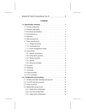
Medalist XE Family Product Manual, Rev. B iii Contents 1.0 Specification summary 1 1.1 Format configuration 1 1.2 Physical organization 2 1.3 Functional specifications 3 1.4 Drive dimensions 3 1.5 Seek time 3 1.6 Start and stop time 4 1.7 Power specifications 4 1.7.1 Voltage tolerances 4 1.7.2 Conducted noise 5 1.7.3 Power-management modes 5 1.8 Environment 7... precautions 11 2.2 The ATA interface connector 12 2.3 Power connector 12 2.4 Master/slave jumper block 12 2.4.1 Single-drive configuration 13 2.4.2 Two-drive configuration 13 2.4.3 Cable-select configuration 14
Medalist XE Family Product Manual, Rev. B iii Contents 1.0 Specification summary 1 1.1 Format configuration 1 1.2 Physical organization 2 1.3 Functional specifications 3 1.4 Drive dimensions 3 1.5 Seek time 3 1.6 Start and stop time 4 1.7 Power specifications 4 1.7.1 Voltage tolerances 4 1.7.2 Conducted noise 5 1.7.3 Power-management modes 5 1.8 Environment 7... precautions 11 2.2 The ATA interface connector 12 2.3 Power connector 12 2.4 Master/slave jumper block 12 2.4.1 Single-drive configuration 13 2.4.2 Two-drive configuration 13 2.4.3 Cable-select configuration 14
Product Manual
Page 7
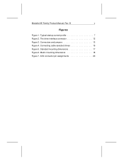
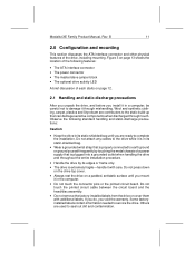
The drive interface connector 12 Figure 3. Standard mounting dimensions 17 Figure 6. Medalist XE Family Product Manual, Rev. Connectors and jumpers 13 Figure 4. Connecting cable-selected drives 15 Figure 5. ATA connector pin assignments 20 Typical startup current profile 7 Figure 2. Metric mounting dimensions 18 Figure 7. B v Figures Figure 1.
The drive interface connector 12 Figure 3. Standard mounting dimensions 17 Figure 6. Medalist XE Family Product Manual, Rev. Connectors and jumpers 13 Figure 4. Connecting cable-selected drives 15 Figure 5. ATA connector pin assignments 20 Typical startup current profile 7 Figure 2. Metric mounting dimensions 18 Figure 7. B v Figures Figure 1.
Product Manual
Page 19
...mounting. Observe the following features: • The ATA interface connector • The power connector • The master/slave jumper block • The optional drive activity LED A brief discussion of a power supply that can damage sensitive components when discharged through mishandling. Figure 3 on ...between the circuit board and the head/disc assembly. • Do not remove the factory-installed labels from the drive or cover them with care. Medalist XE Family Product Manual, Rev. B 11 2.0 Configuration and mounting This section discusses the ATA interface connector and ...
...mounting. Observe the following features: • The ATA interface connector • The power connector • The master/slave jumper block • The optional drive activity LED A brief discussion of a power supply that can damage sensitive components when discharged through mishandling. Figure 3 on ...between the circuit board and the head/disc assembly. • Do not remove the factory-installed labels from the drive or cover them with care. Medalist XE Family Product Manual, Rev. B 11 2.0 Configuration and mounting This section discusses the ATA interface connector and ...
Product Manual
Page 20
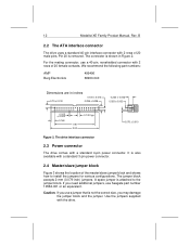
... with a standard 4-pin power connector. The drive interface connector 2.3 Power connector The drive comes with the drive. If you need additional jumpers, use a jumper that is not the correct size, you use Seagate part number 10562-001 or an equivalent. Caution. If you may damage the jumper block and the jumper. 12 Medalist XE Family Product Manual, Rev. For...
... with a standard 4-pin power connector. The drive interface connector 2.3 Power connector The drive comes with the drive. If you need additional jumpers, use a jumper that is not the correct size, you use Seagate part number 10562-001 or an equivalent. Caution. If you may damage the jumper block and the jumper. 12 Medalist XE Family Product Manual, Rev. For...
Product Manual
Page 21
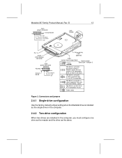
... ATA-compatible master. Cable select Figure 3. The drive is a master; Connectors and jumpers 2.4.1 Single-drive configuration Use the factory-default jumper setting when the Medalist drive is not ATA-compatible. signal. a slave is present, but it is installed as the single drive in the computer. 2.4.2 Two-drive configuration When two drives are installed in the computer, you must configure...
... ATA-compatible master. Cable select Figure 3. The drive is a master; Connectors and jumpers 2.4.1 Single-drive configuration Use the factory-default jumper setting when the Medalist drive is not ATA-compatible. signal. a slave is present, but it is installed as the single drive in the computer. 2.4.2 Two-drive configuration When two drives are installed in the computer, you must configure...
Product Manual
Page 22
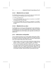
... not carried to the DASP- B 2.4.2.1 Medalist drive as master The Medalist drives provide for three ways the slave can configure the Medalist drive for a slave that is ready 2.4.2.2 Medalist drive as shown in this position, the drive ignores the jumper installed on page 13. when the drive is : • An ATA-compatible drive • A non-ATA-compatible drive that does not conform to...
... not carried to the DASP- B 2.4.2.1 Medalist drive as master The Medalist drives provide for three ways the slave can configure the Medalist drive for a slave that is ready 2.4.2.2 Medalist drive as shown in this position, the drive ignores the jumper installed on page 13. when the drive is : • An ATA-compatible drive • A non-ATA-compatible drive that does not conform to...
Product Manual
Page 23
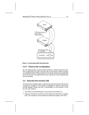
... mounted directly on pins 5 and 6 and pins 7 and 8 at computer Computer Figure 4. Medalist XE Family Product Manual, Rev. B 15 Slave CSEL not carried to test the drive at the factory. Connecting cable-selected drives 2.4.4 Factory-test configuration Do not install jumpers on the printed circuit board, or • A two-pin header is nearest the...
... mounted directly on pins 5 and 6 and pins 7 and 8 at computer Computer Figure 4. Medalist XE Family Product Manual, Rev. B 15 Slave CSEL not carried to test the drive at the factory. Connecting cable-selected drives 2.4.4 Factory-test configuration Do not install jumpers on the printed circuit board, or • A two-pin header is nearest the...


