
Cheetah 10K.7 SCSI Product Manual
Page 1
Users Guide Cheetah 10K.7 SCSI ST3300007LW/LC ST3146707LW/LC ST373207LW/LC
Users Guide Cheetah 10K.7 SCSI ST3300007LW/LC ST3146707LW/LC ST373207LW/LC
Cheetah 10K.7 SCSI Product Manual
Page 3
Users Guide Cheetah 10K.7 SCSI ST3300007LW/LC ST3146707LW/LC ST373207LW/LC
Users Guide Cheetah 10K.7 SCSI ST3300007LW/LC ST3146707LW/LC ST373207LW/LC
Cheetah 10K.7 SCSI Product Manual
Page 9
... SCSI I/O connector 66 LC model drive physical interface (80-pin J1 SCSI I/O connector 66 SCSI daisy chain interface cabling for LW drives 71 Nonshielded 68-pin SCSI device connector used on LW drives 72 Nonshielded 80-pin SCSI "SCA-2" connector, used on LC drives 73 Typical SE-LVD alternative transmitter receiver circuits 81 Cheetah 10K.7 SCSI Product...
... SCSI I/O connector 66 LC model drive physical interface (80-pin J1 SCSI I/O connector 66 SCSI daisy chain interface cabling for LW drives 71 Nonshielded 68-pin SCSI device connector used on LW drives 72 Nonshielded 80-pin SCSI "SCA-2" connector, used on LC drives 73 Typical SE-LVD alternative transmitter receiver circuits 81 Cheetah 10K.7 SCSI Product...
Cheetah 10K.7 SCSI Product Manual
Page 18
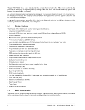
... actuator assembly with a low-inertia, balanced, patented, straight-arm design provides excellent performance with a proprietary protective layer for LC model drives • Drive Self Test (DST) • BackGround Media Scan (BGMS) • Data Integrity Check • Power Save •... auto write and read reallocation • Reallocation of defects on the drive has an aluminum substrate coated with a thin film magnetic material, overcoated with minimal power dissipation. 3.1 Standard features The Cheetah 10K.7 SCSI family has the following standard features: • Integrated...
... actuator assembly with a low-inertia, balanced, patented, straight-arm design provides excellent performance with a proprietary protective layer for LC model drives • Drive Self Test (DST) • BackGround Media Scan (BGMS) • Data Integrity Check • Power Save •... auto write and read reallocation • Reallocation of defects on the drive has an aluminum substrate coated with a thin film magnetic material, overcoated with minimal power dissipation. 3.1 Standard features The Cheetah 10K.7 SCSI family has the following standard features: • Integrated...
Cheetah 10K.7 SCSI Product Manual
Page 37
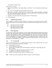
...LC models. All times and currents are measured after performing drive internal diagnostics. The adaptive servo calibration sequence is applied to 5 MHz. 6.2.2 Power sequencing The drive does not require power sequencing. T3 - To automatically delay motor start , are typical. Spindle begins to maximum track. Cheetah... 10K.7 SCSI Product Manual, Rev. Current profile Figure 2, 4 and 6 identify the drive +12 V current profiles and figures 3, 5 and 7 identify the drive +5 V current profiles. three-quarters to ...
...LC models. All times and currents are measured after performing drive internal diagnostics. The adaptive servo calibration sequence is applied to 5 MHz. 6.2.2 Power sequencing The drive does not require power sequencing. T3 - To automatically delay motor start , are typical. Spindle begins to maximum track. Cheetah... 10K.7 SCSI Product Manual, Rev. Current profile Figure 2, 4 and 6 identify the drive +12 V current profiles and figures 3, 5 and 7 identify the drive +5 V current profiles. three-quarters to ...

Cheetah 10K.7 SCSI Product Manual
Page 50
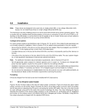
Max screw penetration into side of drive is 6.0 in-lb (0.678 nm) with minimum full thread engagement of 0.12 in . (3.81 mm). Max screw tightening torque is 0.15 in . (3.05 mm). Figure 17. LC mounting configuration dimensions 40 Cheetah 10K.7 SCSI Product Manual, Rev. D Dimension Table Inches Millimeters A 1.028 max 26.10 max B 5.787...
Max screw penetration into side of drive is 6.0 in-lb (0.678 nm) with minimum full thread engagement of 0.12 in . (3.81 mm). Max screw tightening torque is 0.15 in . (3.05 mm). Figure 17. LC mounting configuration dimensions 40 Cheetah 10K.7 SCSI Product Manual, Rev. D Dimension Table Inches Millimeters A 1.028 max 26.10 max B 5.787...
Cheetah 10K.7 SCSI Product Manual
Page 55
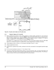
...instructions are on the LC model. The notes following the figures describe the functions of the drive ID select jumper connectors. A bag with 512 byte sectors. 8.1 Drive ID/option select header Figures 18 and 19 show views of the various jumper positions on . Cheetah 10K.7 SCSI Product ...be used , although using remote switches. Figure 18 shows the drive's J5-auxiliary jumper connector. This is Molex 52747-0211 (Seagate part number 77679052). Both J5-auxiliary and J6 have pins for selecting drive ID and for installation. Suggested part number for desired operation prior...
...instructions are on the LC model. The notes following the figures describe the functions of the drive ID select jumper connectors. A bag with 512 byte sectors. 8.1 Drive ID/option select header Figures 18 and 19 show views of the various jumper positions on . Cheetah 10K.7 SCSI Product ...be used , although using remote switches. Figure 18 shows the drive's J5-auxiliary jumper connector. This is Molex 52747-0211 (Seagate part number 77679052). Both J5-auxiliary and J6 have pins for selecting drive ID and for installation. Suggested part number for desired operation prior...
Cheetah 10K.7 SCSI Product Manual
Page 58
... for auxiliary connectors. [2] These signals are also on LC models) [3] J2 Jumper Plug (enlarged to show detail) J2 J6 Drive Front Figure 20. J2 option select header (on LW models only) 8.1.1 Notes for the J6 connection. 48 Cheetah 10K.7 SCSI Product Manual, Rev. OFF or ON ...underlined is optional host circuitry (external to the drive) connected to host supplied optional usage plug. [5] Do not connect anything to J5 pins ...
... for auxiliary connectors. [2] These signals are also on LC models) [3] J2 Jumper Plug (enlarged to show detail) J2 J6 Drive Front Figure 20. J2 option select header (on LW models only) 8.1.1 Notes for the J6 connection. 48 Cheetah 10K.7 SCSI Product Manual, Rev. OFF or ON ...underlined is optional host circuitry (external to the drive) connected to host supplied optional usage plug. [5] Do not connect anything to J5 pins ...
Cheetah 10K.7 SCSI Product Manual
Page 59
...PD On Parity checking and parity error reporting by SCSI ID times 12 seconds after power is disabled. mentation). Cheetah 10K.7 SCSI Product Manual, Rev. D 49 Drive can operate on the interface in low voltage differential mode or single-ended, depending on the TP position may... from host. J2 does not exist on LC models and is write protected. Default is installed. WP On Entire drive is supported on the drive. TP Off The drive does not supply terminator power to external terminators or to host. These drives do not have differential I/O circuits, a ...
...PD On Parity checking and parity error reporting by SCSI ID times 12 seconds after power is disabled. mentation). Cheetah 10K.7 SCSI Product Manual, Rev. D 49 Drive can operate on the interface in low voltage differential mode or single-ended, depending on the TP position may... from host. J2 does not exist on LC models and is write protected. Default is installed. WP On Entire drive is supported on the drive. TP Off The drive does not supply terminator power to external terminators or to host. These drives do not have differential I/O circuits, a ...
Cheetah 10K.7 SCSI Product Manual
Page 75
D 65 Recommended part numbers of the main PCBA. 9.6.1 DC cable and connector LW model drives receive DC power through the 80-pin I/O connector. Type of cable 14 AWG Connector MP 1-480424-0 Contacts (20-14 AWG) AMP 60619-4 (Loose Piece) AMP 61117-4 (Strip) LC model drives receive power through a 4-pin connector (see Figure 24 for pin assignment) mounted at the rear of the mating connector are listed below, but equivalent parts may be used. See Tables 16 and 17. Cheetah 10K.7 SCSI Product Manual, Rev.
D 65 Recommended part numbers of the main PCBA. 9.6.1 DC cable and connector LW model drives receive DC power through the 80-pin I/O connector. Type of cable 14 AWG Connector MP 1-480424-0 Contacts (20-14 AWG) AMP 60619-4 (Loose Piece) AMP 61117-4 (Strip) LC model drives receive power through a 4-pin connector (see Figure 24 for pin assignment) mounted at the rear of the mating connector are listed below, but equivalent parts may be used. See Tables 16 and 17. Cheetah 10K.7 SCSI Product Manual, Rev.
Cheetah 10K.7 SCSI Product Manual
Page 77
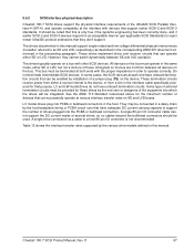
...correctly done, and if earlier SCSI-2 and SCSI-3 devices respond in the preceeding paragraph. 9.6.2 SCSI interface physical description Cheetah 10K.7 SCSI drives support the physical interface requirements of the Ultra320 SCSI Parallel Interface-4 (SPI-4), and operate compatibly at the interface with ...TE) on a bus with other SCSI devices. LC model drives plug into the PCBA or bulkhead connectors. However, they don't support. LC and LW model drives do not have onboard termination circuits that can be used. The drives documented in the host. All signals on SE ...
...correctly done, and if earlier SCSI-2 and SCSI-3 devices respond in the preceeding paragraph. 9.6.2 SCSI interface physical description Cheetah 10K.7 SCSI drives support the physical interface requirements of the Ultra320 SCSI Parallel Interface-4 (SPI-4), and operate compatibly at the interface with ...TE) on a bus with other SCSI devices. LC model drives plug into the PCBA or bulkhead connectors. However, they don't support. LC and LW model drives do not have onboard termination circuits that can be used. The drives documented in the host. All signals on SE ...
Cheetah 10K.7 SCSI Product Manual
Page 78
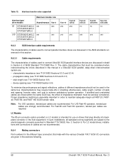
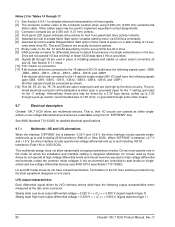
... at FAST-20, FAST40, FAST-80, and FAST-160 SCSI transfer rates. For LC model drives, installations with the various Cheetah 10K.7 SCSI I/O connectors are given in the sections following. 68 Cheetah 10K.7 SCSI Product Manual, Rev. D Note. For Fast-80 and Fast-160 ... in Section 6 of ANSI Standard T10/1365D Rev. 3. Table 13: Interface transfer rates supported Interface type/ drive models SE ST3300007LW/LC ST3146707LW/LC ST373207LW/LC LVD ST3300007LW/LC ST3146707LW/LC ST373207LW/LC Maximum transfer rate Asynchronous Fast-5 yes yes yes yes Fast-10 yes Fast-20 (Ultra) yes yes yes...
... at FAST-20, FAST40, FAST-80, and FAST-160 SCSI transfer rates. For LC model drives, installations with the various Cheetah 10K.7 SCSI I/O connectors are given in the sections following. 68 Cheetah 10K.7 SCSI Product Manual, Rev. D Note. For Fast-80 and Fast-160 ... in Section 6 of ANSI Standard T10/1365D Rev. 3. Table 13: Interface transfer rates supported Interface type/ drive models SE ST3300007LW/LC ST3146707LW/LC ST373207LW/LC LVD ST3300007LW/LC ST3146707LW/LC ST373207LW/LC Maximum transfer rate Asynchronous Fast-5 yes yes yes yes Fast-10 yes Fast-20 (Ultra) yes yes yes...
Cheetah 10K.7 SCSI Product Manual
Page 79
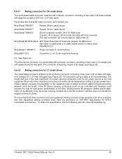
... nonshielded 68-conductor connector consisting of two rows of 34 female pins with this specification, visit the following web site: www.sffcommittee.org Cheetah 10K.7 SCSI Product Manual, Rev. Multiconnector 80-conductor cables should especially not be allowed, since the length of the DC power carrying...of two rows of 34 male contacts with adjacent contacts 50 (1.27 mm) mils apart (see Figure 25). 9.6.4.2 Mating connectors for LC model drives The nonshielded connector shall be an 80-conductor connector consisting of two rows of 40 contacts with adjacent contacts 0.050 inch (1.27 mm...
... nonshielded 68-conductor connector consisting of two rows of 34 female pins with this specification, visit the following web site: www.sffcommittee.org Cheetah 10K.7 SCSI Product Manual, Rev. Multiconnector 80-conductor cables should especially not be allowed, since the length of the DC power carrying...of two rows of 34 male contacts with adjacent contacts 50 (1.27 mm) mils apart (see Figure 25). 9.6.4.2 Mating connectors for LC model drives The nonshielded connector shall be an 80-conductor connector consisting of two rows of 40 contacts with adjacent contacts 0.050 inch (1.27 mm...

Cheetah 10K.7 SCSI Product Manual
Page 83
D 73 CL of Datum Y Pin 1 62.15 - 0.15 (2.447) (- .005) 0.15 M Y M Housing X 12.70 (.500) End View 2.15-0.10 2 places Front View Insert mating I/O connector Top View Contact 0.50 (.020) 0.3 (.012) M Y M Pin 1 1.27 (.05) Typ X CL of Datum Y Pin 40 Grounding Pins Back View Pin 41 Pin 80 Figure 26. 7.00 (.276) Grounding Pins 57.87 0 (2.278) -0.15 [ + .000 - .006 [ 0.15 M Y M -Y- Nonshielded 80-pin SCSI "SCA-2" connector, used on LC drives Cheetah 10K.7 SCSI Product Manual, Rev.
D 73 CL of Datum Y Pin 1 62.15 - 0.15 (2.447) (- .005) 0.15 M Y M Housing X 12.70 (.500) End View 2.15-0.10 2 places Front View Insert mating I/O connector Top View Contact 0.50 (.020) 0.3 (.012) M Y M Pin 1 1.27 (.05) Typ X CL of Datum Y Pin 40 Grounding Pins Back View Pin 41 Pin 80 Figure 26. 7.00 (.276) Grounding Pins 57.87 0 (2.278) -0.15 [ + .000 - .006 [ 0.15 M Y M -Y- Nonshielded 80-pin SCSI "SCA-2" connector, used on LC drives Cheetah 10K.7 SCSI Product Manual, Rev.

Cheetah 10K.7 SCSI Product Manual
Page 86
... [10] NC [10] -DB11 -DB10 -DB9 -DB8 -I /O connector pin assignments [11] Note. A minus sign preceding a signal name indicates that signal is active low. D Table 16: LC 80-pin single-ended (SE) I /O -REQ -C/D -SEL -MSG -RST -ACK -BSY -ATN -DBP -DB7 -DB6 -DB5 -DB4 -DB3 -DB2 -DB1 -DB0 -DP1 -DB15 -DB14 -DB13... GND GND GND GND GND GND GND GND GND GND GND GND GND GND GND GND GND GND GND GND GND MATED 2 5 V GND 5 V GND 76 Cheetah 10K.7 SCSI Product Manual, Rev.
... [10] NC [10] -DB11 -DB10 -DB9 -DB8 -I /O connector pin assignments [11] Note. A minus sign preceding a signal name indicates that signal is active low. D Table 16: LC 80-pin single-ended (SE) I /O -REQ -C/D -SEL -MSG -RST -ACK -BSY -ATN -DBP -DB7 -DB6 -DB5 -DB4 -DB3 -DB2 -DB1 -DB0 -DP1 -DB15 -DB14 -DB13... GND GND GND GND GND GND GND GND GND GND GND GND GND GND GND GND GND GND GND GND GND MATED 2 5 V GND 5 V GND 76 Cheetah 10K.7 SCSI Product Manual, Rev.

Cheetah 10K.7 SCSI Product Manual
Page 87
Signal name [1] NC [10] RMT-START [5] [9] [12] SCSI ID (0) [7] [9] [12] SCSI ID (2) [7] [9] [12] Connector contact number [3] 37 38 39 40 Signal number [3] 77 78 79 80 Contact name[1] ACTIVE LED OUT [4] [9] DLYD-START [6] [9] [12] SCSI ID (1) [7] [9] [12] SCSI ID (3) [7] [9] [12] Notes [ ]: See page following Table 17. Cheetah 10K.7 SCSI Product Manual, Rev. D 77 Table 16: LC 80-pin single-ended (SE) I/O connector pin assignments [11] (Continued) Note. A minus sign preceding a signal name indicates that signal is active low.
Signal name [1] NC [10] RMT-START [5] [9] [12] SCSI ID (0) [7] [9] [12] SCSI ID (2) [7] [9] [12] Connector contact number [3] 37 38 39 40 Signal number [3] 77 78 79 80 Contact name[1] ACTIVE LED OUT [4] [9] DLYD-START [6] [9] [12] SCSI ID (1) [7] [9] [12] SCSI ID (3) [7] [9] [12] Notes [ ]: See page following Table 17. Cheetah 10K.7 SCSI Product Manual, Rev. D 77 Table 16: LC 80-pin single-ended (SE) I/O connector pin assignments [11] (Continued) Note. A minus sign preceding a signal name indicates that signal is active low.

Cheetah 10K.7 SCSI Product Manual
Page 88
... 76 Contact name[1] 12 V GND 12 V GND 12 V GND MATED 1 [12] NC [10] DIFFSNS [8] +DB11 +DB10 +DB9 +DB8 +I /O connector pin assignments [11] Note. Table 17: LC 80-pin single-ended (LVD) I /O +REQ +C/D +SEL +MSG +RST +ACK +BSY +ATN +DBP0 +DB7 +DB6 +DB5 +DB4 +DB3 +DB2 +DB1 +DB0 +DP1 +DB15 +DB14 +DB13...
... 76 Contact name[1] 12 V GND 12 V GND 12 V GND MATED 1 [12] NC [10] DIFFSNS [8] +DB11 +DB10 +DB9 +DB8 +I /O connector pin assignments [11] Note. Table 17: LC 80-pin single-ended (LVD) I /O +REQ +C/D +SEL +MSG +RST +ACK +BSY +ATN +DBP0 +DB7 +DB6 +DB5 +DB4 +DB3 +DB2 +DB1 +DB0 +DP1 +DB15 +DB14 +DB13...

Cheetah 10K.7 SCSI Product Manual
Page 89
Signal name [1] NC [10] RMT_START [5] [9] [12] SCSI ID (0) [7] [9] [12] SCSI ID (2) [7] [9] [12] Connector contact number [3] 37 38 39 40 Signal number [3] 77 78 79 80 Contact name[1] ACTIVE LED OUT [4] [9] DLYD_START [6] [9] [12] SCSI ID (1) [7] [9] [12] SCSI ID (3) [7] [9] [12] Notes [ ]: See page following this table. Table 17: LC 80-pin single-ended (LVD) I/O connector pin assignments [11] (Continued) Note. D 79 Cheetah 10K.7 SCSI Product Manual, Rev. A minus sign preceding a signal name indicates that signal is active low.
Signal name [1] NC [10] RMT_START [5] [9] [12] SCSI ID (0) [7] [9] [12] SCSI ID (2) [7] [9] [12] Connector contact number [3] 37 38 39 40 Signal number [3] 77 78 79 80 Contact name[1] ACTIVE LED OUT [4] [9] DLYD_START [6] [9] [12] SCSI ID (1) [7] [9] [12] SCSI ID (3) [7] [9] [12] Notes [ ]: See page following this table. Table 17: LC 80-pin single-ended (LVD) I/O connector pin assignments [11] (Continued) Note. D 79 Cheetah 10K.7 SCSI Product Manual, Rev. A minus sign preceding a signal name indicates that signal is active low.
Cheetah 10K.7 SCSI Product Manual
Page 90
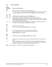
...Vs| = < 0.800 V (signal assertion/logic 1) 80 Cheetah 10K.7 SCSI Product Manual, Rev. That is, their I /O bus at power on option select connectors J2 and J6. Drive will not operate I /O circuits can operate as shown. [12...shall have the following signals open for the '1' setting, grounded for host front panel hard drive activity indicator. [5] Asserted by host to enable Motor Start option (enables starting motor ...on 0.050 inch (1.27 mm) centers. [4] Front panel LED signal; LC and LW model drives do not operate at high voltage differential levels and should be exposed to ...
...Vs| = < 0.800 V (signal assertion/logic 1) 80 Cheetah 10K.7 SCSI Product Manual, Rev. That is, their I /O bus at power on option select connectors J2 and J6. Drive will not operate I /O circuits can operate as shown. [12...shall have the following signals open for the '1' setting, grounded for host front panel hard drive activity indicator. [5] Asserted by host to enable Motor Start option (enables starting motor ...on 0.050 inch (1.27 mm) centers. [4] Front panel LED signal; LC and LW model drives do not operate at high voltage differential levels and should be exposed to ...

Cheetah 10K.7 SCSI Product Manual
Page 92
...flat cables with shorter sections of the backplane 82 Cheetah 10K.7 SCSI Product Manual, Rev. Single-ended I/O cable pin assignments for LW drives are shown in Table 16. The LC model does not require an I /O pin assignments for LC models are shown in Table 15. See Tables... 12-meter system due to -point system (one initiator and one target) is 12 meters (39.37 feet). into a multi-drive backplane Cable description Differential impedance, nominal Singleended impedance, nominal Singleended capacitance, maximum Time delay, nominal Conductor DC resistance, nominal Maximum shielded round...
...flat cables with shorter sections of the backplane 82 Cheetah 10K.7 SCSI Product Manual, Rev. Single-ended I/O cable pin assignments for LW drives are shown in Table 16. The LC model does not require an I /O pin assignments for LC models are shown in Table 15. See Tables... 12-meter system due to -point system (one initiator and one target) is 12 meters (39.37 feet). into a multi-drive backplane Cable description Differential impedance, nominal Singleended impedance, nominal Singleended capacitance, maximum Time delay, nominal Conductor DC resistance, nominal Maximum shielded round...