Cheetah 10K.7 SCSI Product Manual
Page 9
...19. Figure 25. Cheetah 10K.7 SCSI family drive (ST3300007LC shown 1 Typical ST3300007 drive +12 V current profile 28 Typical ST3300007 drive +5 V current profile 28 Typical ST3146707 drive +12 V current profile 29 Typical ST3146707 drive +5 V current profile 29 Typical ST373207 drive +12 V current profile 30 Typical ST373207 drive +5 V current ... check point 34 Recommended mounting 36 LW mounting configuration dimensions 39 LC mounting configuration dimensions 40 J6 jumper header 46 J5 jumper header (on LW models only 47 J2 option select header (on LW models only 48 Air flow ...
...19. Figure 25. Cheetah 10K.7 SCSI family drive (ST3300007LC shown 1 Typical ST3300007 drive +12 V current profile 28 Typical ST3300007 drive +5 V current profile 28 Typical ST3146707 drive +12 V current profile 29 Typical ST3146707 drive +5 V current profile 29 Typical ST373207 drive +12 V current profile 30 Typical ST373207 drive +5 V current ... check point 34 Recommended mounting 36 LW mounting configuration dimensions 39 LC mounting configuration dimensions 40 J6 jumper header 46 J5 jumper header (on LW models only 47 J2 option select header (on LW models only 48 Air flow ...

Cheetah 10K.7 SCSI Product Manual
Page 20
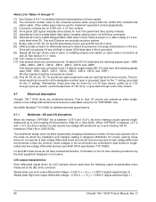
... not change its capacity to something less than maximum. The factory also ships with the drive a small bag of jumper plugs used for the J2, J5, and J6 option select jumper headers on LW models only. 3.7 Options (factory installed) All customer requested options are (not an exhaustive list of ... by the single unit shipping pack. See the Mode Select Parameter List table in the field. • Single unit shipping pack. 10 Cheetah 10K.7 SCSI Product Manual, Rev. All accessories may be installed in the SCSI Interface Product Manual. Users planning single unit distribution should specify...
... not change its capacity to something less than maximum. The factory also ships with the drive a small bag of jumper plugs used for the J2, J5, and J6 option select jumper headers on LW models only. 3.7 Options (factory installed) All customer requested options are (not an exhaustive list of ... by the single unit shipping pack. See the Mode Select Parameter List table in the field. • Single unit shipping pack. 10 Cheetah 10K.7 SCSI Product Manual, Rev. All accessories may be installed in the SCSI Interface Product Manual. Users planning single unit distribution should specify...
Cheetah 10K.7 SCSI Product Manual
Page 55
... 20 shows the option select jumper connector for all appropriate option jumpers for Seagate support services telephone numbers. • Do not remove the manufacturer's installed labels from the factory low level formatted with any additionally purchased drive installation software. Only one that... the various jumper positions on a high voltage differential (HVD) bus. This is Molex 52747-0211 (Seagate part number 77679052). Suggested part number for installation. Refer to the end of the drive is shipped with additional labels, as the host adapter. Cheetah 10K.7 SCSI...
... 20 shows the option select jumper connector for all appropriate option jumpers for Seagate support services telephone numbers. • Do not remove the manufacturer's installed labels from the factory low level formatted with any additionally purchased drive installation software. Only one that... the various jumper positions on a high voltage differential (HVD) bus. This is Molex 52747-0211 (Seagate part number 77679052). Suggested part number for installation. Refer to the end of the drive is shipped with additional labels, as the host adapter. Cheetah 10K.7 SCSI...
Cheetah 10K.7 SCSI Product Manual
Page 56
Figure 18. J6 jumper header 46 Cheetah 10K.7 SCSI Product Manual, Rev. D Do not install jumpers; retain cover. +5V Ground [6] Drive Activity LED [4] Dashed area is optional host circuitry (external to the drive) connected to host supplied optional usage plug. [5] Do not connect anything to pins 13-20. Drive Front J6 [1] Pin 1 SCSI ID = 0 SCSI ID = 1 SCSI...
Figure 18. J6 jumper header 46 Cheetah 10K.7 SCSI Product Manual, Rev. D Do not install jumpers; retain cover. +5V Ground [6] Drive Activity LED [4] Dashed area is optional host circuitry (external to the drive) connected to host supplied optional usage plug. [5] Do not connect anything to pins 13-20. Drive Front J6 [1] Pin 1 SCSI ID = 0 SCSI ID = 1 SCSI...
Cheetah 10K.7 SCSI Product Manual
Page 57
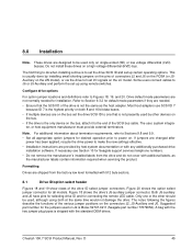
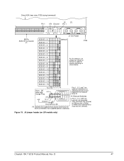
...Plug N.C. 11 9 7 5 3 1 A0 A1 A2 A3 +5V 12 10 8 6 4 2 +5V N.C. J5 jumper header (on LW models only) Cheetah 10K.7 SCSI Product Manual, Rev. Pins 1, 3, 5, and 7 are driven low (ground) for remote switching as shown below. Drive HDA (rear view, PCB facing downward) J5 [1] Pin 1 +5V Ground Pin 1 4P 3P 2P...ID = 11 SCSI ID = 12 SCSI ID = 13 (default) PCB For ID selection use jumpers as shown or connect a cable for 250 ms after a Reset or PWR ON to allow drive to read SCSI ID selected. They are optional connections to switching circuits in host equipment to host ...
...Plug N.C. 11 9 7 5 3 1 A0 A1 A2 A3 +5V 12 10 8 6 4 2 +5V N.C. J5 jumper header (on LW models only) Cheetah 10K.7 SCSI Product Manual, Rev. Pins 1, 3, 5, and 7 are driven low (ground) for remote switching as shown below. Drive HDA (rear view, PCB facing downward) J5 [1] Pin 1 +5V Ground Pin 1 4P 3P 2P...ID = 11 SCSI ID = 12 SCSI ID = 13 (default) PCB For ID selection use jumpers as shown or connect a cable for 250 ms after a Reset or PWR ON to allow drive to read SCSI ID selected. They are optional connections to switching circuits in host equipment to host ...
Cheetah 10K.7 SCSI Product Manual
Page 58
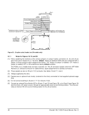
... 8.1.2. The J5 connector signals conform to LW models only; The PCBA on LW models only) 8.1.1 Notes for the J6 connection. 48 Cheetah 10K.7 SCSI Product Manual, Rev. J2 Pin 1 RR Jumper S D M W P E E T Positions E S E P D S S P Force single-ended bus mode Delay Motor Start [2] Enable Remote Motor Start Write ...not connect anything to J5 pins 9, 11-12 or J6 pins 13-20. [6] Connect an external Drive Activity LED to J6 pins 11 and 12 (see Figure 19) and the drives +5V power source, through an appropriately sized current limiting resistor. Reserved Term. J2 option select header ...
... 8.1.2. The J5 connector signals conform to LW models only; The PCBA on LW models only) 8.1.1 Notes for the J6 connection. 48 Cheetah 10K.7 SCSI Product Manual, Rev. J2 Pin 1 RR Jumper S D M W P E E T Positions E S E P D S S P Force single-ended bus mode Delay Motor Start [2] Enable Remote Motor Start Write ...not connect anything to J5 pins 9, 11-12 or J6 pins 13-20. [6] Connect an external Drive Activity LED to J6 pins 11 and 12 (see Figure 19) and the drives +5V power source, through an appropriately sized current limiting resistor. Reserved Term. J2 option select header ...
Cheetah 10K.7 SCSI Product Manual
Page 59
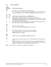
... single-ended I/O drivers/receivers only. Cheetah 10K.7 SCSI Product Manual, Rev. Default setting. Spindle Startup is delayed by the drive is applied, i.e., drive 0 spindle starts immediately when DC power connected, drive 1 starts after 12 second delay, drive 2 starts after power up - Default is SE jumper not installed. Off Drive is PD jumper not installed. Default is not write...
... single-ended I/O drivers/receivers only. Cheetah 10K.7 SCSI Product Manual, Rev. Default setting. Spindle Startup is delayed by the drive is applied, i.e., drive 0 spindle starts immediately when DC power connected, drive 1 starts after 12 second delay, drive 2 starts after power up - Default is SE jumper not installed. Off Drive is PD jumper not installed. Default is not write...

Cheetah 10K.7 SCSI Product Manual
Page 64
...following lists the SCSI interface commands that are shipped set to operate in Ultra320 mode. Table 5: Commands supported by Cheetah 10K.7 SCSI family drives (Continued) Message name Message code Release recovery 10h Restore pointers 03h Save data pointer 02h Synchronous data transfer req....Def page (81h) Jumper Settings page (C2h) Supported Vital Product Data page (00h) Unit Serial Number page (80h) Lock-unlock cache Log Select PCR bit DU bit Command code 40h 39h 18h 3Ah 04h 12h 36h 4Ch Supported N N N N Y N Y Y Y Y Y N Y Y Y Y Y Y Y Y N Y Y N 54 Cheetah 10K.7 SCSI Product Manual...
...following lists the SCSI interface commands that are shipped set to operate in Ultra320 mode. Table 5: Commands supported by Cheetah 10K.7 SCSI family drives (Continued) Message name Message code Release recovery 10h Restore pointers 03h Save data pointer 02h Synchronous data transfer req....Def page (81h) Jumper Settings page (C2h) Supported Vital Product Data page (00h) Unit Serial Number page (80h) Lock-unlock cache Log Select PCR bit DU bit Command code 40h 39h 18h 3Ah 04h 12h 36h 4Ch Supported N N N N Y N Y Y Y Y Y N Y Y Y Y Y Y Y Y N Y Y N 54 Cheetah 10K.7 SCSI Product Manual...
Cheetah 10K.7 SCSI Product Manual
Page 77
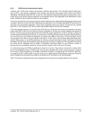
...all devices on the bus. A single drive connected via a cable to a host 80-pin I /O connector cable cannot support the DC current needs of several drives, so no cables beyond the bulkhead connectors should be enabled by installation of a jumper plug (TE) on the bus must... and SCSI-3 standards. All signals on the bus are common between SE and LVD operation. Cheetah 10K.7 SCSI Product Manual, Rev. 9.6.2 SCSI interface physical description Cheetah 10K.7 SCSI drives support the physical interface requirements of the Ultra320 SCSI Parallel Interface-4 (SPI-4), and operate compatibly at...
...all devices on the bus. A single drive connected via a cable to a host 80-pin I /O connector cable cannot support the DC current needs of several drives, so no cables beyond the bulkhead connectors should be enabled by installation of a jumper plug (TE) on the bus must... and SCSI-3 standards. All signals on the bus are common between SE and LVD operation. Cheetah 10K.7 SCSI Product Manual, Rev. 9.6.2 SCSI interface physical description Cheetah 10K.7 SCSI drives support the physical interface requirements of the Ultra320 SCSI Parallel Interface-4 (SPI-4), and operate compatibly at...
Cheetah 10K.7 SCSI Product Manual
Page 90
...Steady state High level output differential voltage = 0.320 V = < |Vs| = < 0.800 V (signal assertion/logic 1) 80 Cheetah 10K.7 SCSI Product Manual, Rev. Termination of a single ended device on the bus. See Section 8.1.1 notes. [10] "NC... a pull-up SCSI bus ID in the mode for host front panel hard drive activity indicator. [5] Asserted by host to enable Motor Start option (enables ...grounded. [9] Signals [4] through 17. [1] See Section 9.6.4.1 for detailed electrical characteristics of installing jumpers and cables on 0.050 inch (1.27 mm) centers. [4] Front panel LED signal; See ...
...Steady state High level output differential voltage = 0.320 V = < |Vs| = < 0.800 V (signal assertion/logic 1) 80 Cheetah 10K.7 SCSI Product Manual, Rev. Termination of a single ended device on the bus. See Section 8.1.1 notes. [10] "NC... a pull-up SCSI bus ID in the mode for host front panel hard drive activity indicator. [5] Asserted by host to enable Motor Start option (enables ...grounded. [9] Signals [4] through 17. [1] See Section 9.6.4.1 for detailed electrical characteristics of installing jumpers and cables on 0.050 inch (1.27 mm) centers. [4] Front panel LED signal; See ...

Cheetah 10K.7 SCSI Product Manual
Page 93
Cheetah 10K.7 SCSI Product Manual, Rev. LC drives are devoted to terminator power. Table 20: Example Twist-n-flat cables - LC drives These drives cannot furnish terminator power because no conductors in the 80-pin I /O cable stub extending past the last cable connector....manufacturer must provide a terminator arrangement external to the external terminator. For LW drives, terminator modules can configure terminator power from the drive to place jumpers for illustrations that plug between the SCSI I/O cable and the drive I/O connector or on the end of a short I /O connector are ...
Cheetah 10K.7 SCSI Product Manual, Rev. LC drives are devoted to terminator power. Table 20: Example Twist-n-flat cables - LC drives These drives cannot furnish terminator power because no conductors in the 80-pin I /O cable stub extending past the last cable connector....manufacturer must provide a terminator arrangement external to the external terminator. For LW drives, terminator modules can configure terminator power from the drive to place jumpers for illustrations that plug between the SCSI I/O cable and the drive I/O connector or on the end of a short I /O connector are ...
Cheetah 10K.7 SCSI Product Manual
Page 104
...drive 37 drive activity 80 drive activity LED 86 drive capacity 11 programmable 10 drive default mode parameter 45 drive failure 18 drive firmware 59 drive ID 45 drive ID select jumper connector 45 drive ID/option select header 45 drive interface connector 69 drive internal 27 drive internal defects and errors 41 drive malfunction 18 drive mounting 38, 51 constraints 17 drive orientation 50 drive power 45 drive... 45 front panel 38 front panel LED 80 G GMR heads 7 gradient 34 ground return 27 grounding 51 H hard reset 59 HDA 7, 51 heat removal 50 host 15, 41, 49, 57, 67, 71 host adapter 45...
...drive 37 drive activity 80 drive activity LED 86 drive capacity 11 programmable 10 drive default mode parameter 45 drive failure 18 drive firmware 59 drive ID 45 drive ID select jumper connector 45 drive ID/option select header 45 drive interface connector 69 drive internal 27 drive internal defects and errors 41 drive malfunction 18 drive mounting 38, 51 constraints 17 drive orientation 50 drive power 45 drive... 45 front panel 38 front panel LED 80 G GMR heads 7 gradient 34 ground return 27 grounding 51 H hard reset 59 HDA 7, 51 heat removal 50 host 15, 41, 49, 57, 67, 71 host adapter 45...
Cheetah 10K.7 SCSI Product Manual
Page 105
... system malfunction 17 host/drive operational interface 17 hot ... 17 internal data rate 11 J J1-auxiliary 45 jumper 10, 45, 48, 49, 80 jumper function description 49 jumper header 48 jumper plug type 45 L landing zone 8 LB 14 ...maximum current requirements 27 maximum operating current 27 maximum starting current 25, 26 ME jumper 49 media 8, 59 message protocol 64 message protocol system 43 messages SCSI interface...environment 18 operating option 45 operating parameter 59 option jumper 45 option jumper location 45 option select header 64 option select jumper 45 options 10 orientation 13, 35, 50 out...
... system malfunction 17 host/drive operational interface 17 hot ... 17 internal data rate 11 J J1-auxiliary 45 jumper 10, 45, 48, 49, 80 jumper function description 49 jumper header 48 jumper plug type 45 L landing zone 8 LB 14 ...maximum current requirements 27 maximum operating current 27 maximum starting current 25, 26 ME jumper 49 media 8, 59 message protocol 64 message protocol system 43 messages SCSI interface...environment 18 operating option 45 operating parameter 59 option jumper 45 option jumper location 45 option select header 64 option select jumper 45 options 10 orientation 13, 35, 50 out...

Cheetah 10K.7 SCSI Product Manual
Page 106
...49 PCB 48 PCBA 45, 51, 59, 65, 67, 70 PCBA circuit run 67 PD jumper 49 peak bits/inch 11 peak starting current 27 performance characteristics 11 performance degradation 35 peripheral I/O cable... cache control 13 preventive maintenance 17, 18 PRML read channel electronics 7 product data page 58 programmable drive capacity 10 R radio interference regulations 3 read 13 read command 13, 14, 15 read data 14...SCSI systems error 43 SCSI systems error consideration 41 SCSI systems error management 43 Seagate support service 45 sector 14 sector interleave 12 sector sizes 12 seek error 17 defined 18 segment...
...49 PCB 48 PCBA 45, 51, 59, 65, 67, 70 PCBA circuit run 67 PD jumper 49 peak bits/inch 11 peak starting current 27 performance characteristics 11 performance degradation 35 peripheral I/O cable... cache control 13 preventive maintenance 17, 18 PRML read channel electronics 7 product data page 58 programmable drive capacity 10 R radio interference regulations 3 read 13 read command 13, 14, 15 read data 14...SCSI systems error 43 SCSI systems error consideration 41 SCSI systems error management 43 Seagate support service 45 sector 14 sector interleave 12 sector sizes 12 seek error 17 defined 18 segment...

Cheetah 10K.7 SCSI Product Manual
Page 107
... vital product data 58 volatile memory 59 voltage 13, 25, 26 W warranty 9, 23 wet bulb temperature 34 wide Ultra320 SCSI interface 7 WP jumper 49 wrap-around 14 write caching 14 write operation 14 write protect 49 write retry count 41 Z zoned bit recording (ZBR) 8 T technical support... services 87 temperature 13, 20, 34, 50 non-operating 34 regulation 3 See also cooling temperature sensor 20 termination 27 terminator enable jumper TE 71 terminator power 83 terminator requirements 45, 83 thermal monitor 20 TP1 position 49 tracks/inch 11 tracks/surface, total 11 transfer period ...
... vital product data 58 volatile memory 59 voltage 13, 25, 26 W warranty 9, 23 wet bulb temperature 34 wide Ultra320 SCSI interface 7 WP jumper 49 wrap-around 14 write caching 14 write operation 14 write protect 49 write retry count 41 Z zoned bit recording (ZBR) 8 T technical support... services 87 temperature 13, 20, 34, 50 non-operating 34 regulation 3 See also cooling temperature sensor 20 termination 27 terminator enable jumper TE 71 terminator power 83 terminator requirements 45, 83 thermal monitor 20 TP1 position 49 tracks/inch 11 tracks/surface, total 11 transfer period ...


