User Manual 5
Page 2
... Symbols...6-7 Electrical...8 Glossary of Terms...9 Features...10-13 Tools Needed ...13 Loose Parts...14 Assembly...15-21 Operation...22-35 Adjustments...36-38 Maintenance...38 Accessories...39 Troubleshooting...39-40 Parts ...within ninety (90) days or less. The replacement power tool will complete the work in a reasonable time, but, in any RYOBI® power tool which vary from misuse, abuse, neglect, alteration, modification or repairs by the limited warranty for a period of ...
... Symbols...6-7 Electrical...8 Glossary of Terms...9 Features...10-13 Tools Needed ...13 Loose Parts...14 Assembly...15-21 Operation...22-35 Adjustments...36-38 Maintenance...38 Accessories...39 Troubleshooting...39-40 Parts ...within ninety (90) days or less. The replacement power tool will complete the work in a reasonable time, but, in any RYOBI® power tool which vary from misuse, abuse, neglect, alteration, modification or repairs by the limited warranty for a period of ...

User Manual 5
Page 11
...LEVER - MITER GAUGE - The miter gauge aligns the wood for rip cuts. SLIDING TABLE EXTENSION - A removable metal piece of the blade guard assembly, slightly thinner than the speed of the saw blade for height adjustments or blade replacement. When in the grooves on the front of the cabinet..., locks the angle setting of kickback. SWITCH ASSEMBLY - Kickback is a hazard in a location that is below the front rail. If the workpiece should be pulled back toward the operator. BLADE ...
...LEVER - MITER GAUGE - The miter gauge aligns the wood for rip cuts. SLIDING TABLE EXTENSION - A removable metal piece of the blade guard assembly, slightly thinner than the speed of the saw blade for height adjustments or blade replacement. When in the grooves on the front of the cabinet..., locks the angle setting of kickback. SWITCH ASSEMBLY - Kickback is a hazard in a location that is below the front rail. If the workpiece should be pulled back toward the operator. BLADE ...
User Manual 5
Page 12
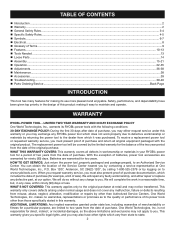
...with the blade before plugging tool into the switch, lift the switch to use the blade guard assembly for the basic cuts: cross cuts, miter cuts, bevel cuts, and compound cuts. The blade guard assembly includes: riving knife/spreader/splitter, anti-kickback pawls, and plastic blade guard. The height of this... to heed this manual for all through the table and is in a safe place. The rip fence is not in contact with a switch assembly that has a built-in serious personal injury. SWITCH ASSEMBLY See Figure 3. TO LOCK YOUR SAW: Press the switch down to start the tool.
...with the blade before plugging tool into the switch, lift the switch to use the blade guard assembly for the basic cuts: cross cuts, miter cuts, bevel cuts, and compound cuts. The blade guard assembly includes: riving knife/spreader/splitter, anti-kickback pawls, and plastic blade guard. The height of this... to heed this manual for all through the table and is in a safe place. The rip fence is not in contact with a switch assembly that has a built-in serious personal injury. SWITCH ASSEMBLY See Figure 3. TO LOCK YOUR SAW: Press the switch down to start the tool.
User Manual 5
Page 13
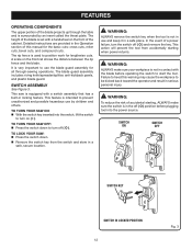
... the limits stamped on the spreader/ riving knife. WARNING: Do not use the 36-tooth, 10 in personal injury. Failure to scale) are available for assembly and making adjustments: FRAMING SQUARE PHILLIPS SCREWDRIVER FLATHEAD SCREWDRIVER COMBINATION SQUARE SOCKET WRENCH AND 10 mm SOCKET C-CLAMPS Fig. 4 13 TOOLS NEEDED The following tools...
... the limits stamped on the spreader/ riving knife. WARNING: Do not use the 36-tooth, 10 in personal injury. Failure to scale) are available for assembly and making adjustments: FRAMING SQUARE PHILLIPS SCREWDRIVER FLATHEAD SCREWDRIVER COMBINATION SQUARE SOCKET WRENCH AND 10 mm SOCKET C-CLAMPS Fig. 4 13 TOOLS NEEDED The following tools...
User Manual 5
Page 14
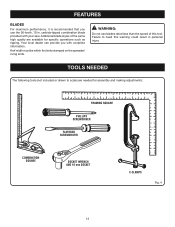
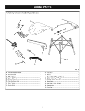
Miter Gauge 1 D. Push Stick 1 Fig. 5 H. Hex Key (3 mm, 5 mm 2 N. Sliding Table Assembly 1 L. End Cap 1 14 Handle Assembly 1 F. Screw 2 J. Dust Bag 1 M. Anti-Kickback Pawls 1 B. Indicator 1 I C E F D J M G A. Quick Stand™ (Leg Stand 1 K. Rip Fence 1 G. Blade Wrench 2 E. LOOSE PARTS The following items are included with your table saw: A L K N B I H O I . Blade Guard 1 C. Switch Key 1 O.
Miter Gauge 1 D. Push Stick 1 Fig. 5 H. Hex Key (3 mm, 5 mm 2 N. Sliding Table Assembly 1 L. End Cap 1 14 Handle Assembly 1 F. Screw 2 J. Dust Bag 1 M. Anti-Kickback Pawls 1 B. Indicator 1 I C E F D J M G A. Quick Stand™ (Leg Stand 1 K. Rip Fence 1 G. Blade Wrench 2 E. LOOSE PARTS The following items are included with your table saw: A L K N B I H O I . Blade Guard 1 C. Switch Key 1 O.
User Manual 5
Page 15
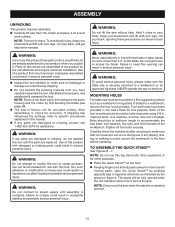
...when the stand is heavy. to a workbench, remove the four locking knobs. The stand will be mounted to your back. ASSEMBLY UNPACKING This product requires assembly. Carefully lift saw from the carton and place it , check for accuracy. NOTE: This tool is completely opened... to a workbench or an approved leg stand. Ignoring these precautions can occur during shipping. Do not discard the packing material until assembly is noted, secure the workbench to come closer than 3 in opposite directions as a workbench or leg stand. WARNING: If any tipping, ...
...when the stand is heavy. to a workbench, remove the four locking knobs. The stand will be mounted to your back. ASSEMBLY UNPACKING This product requires assembly. Carefully lift saw from the carton and place it , check for accuracy. NOTE: This tool is completely opened... to a workbench or an approved leg stand. Ignoring these precautions can occur during shipping. Do not discard the packing material until assembly is noted, secure the workbench to come closer than 3 in opposite directions as a workbench or leg stand. WARNING: If any tipping, ...
User Manual 5
Page 16
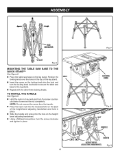
ASSEMBLY RED INDICATOR V SLOT Fig. 6 MOUNTING THE TABLE SAW BASE TO THE QUICK STAND™ See Figure 8. Place the table saw base to the leg ...
ASSEMBLY RED INDICATOR V SLOT Fig. 6 MOUNTING THE TABLE SAW BASE TO THE QUICK STAND™ See Figure 8. Place the table saw base to the leg ...
User Manual 5
Page 17
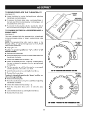
.../bevel adjusting handwheel clockwise. Unlock the release lever by pulling it up " position for all through cutting or "down . Reinstall the throat plate. ASSEMBLY TO REMOVE/REPLACE THE THROAT PLATE See Figure 10. Lower the blade by turning the height/bevel adjusting handwheel counterclockwise. To remove the...
.../bevel adjusting handwheel clockwise. Unlock the release lever by pulling it up " position for all through cutting or "down . Reinstall the throat plate. ASSEMBLY TO REMOVE/REPLACE THE THROAT PLATE See Figure 10. Lower the blade by turning the height/bevel adjusting handwheel counterclockwise. To remove the...
User Manual 5
Page 18
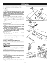
... be installed for free blade rotation. To install anti-kickback pawls: Press and hold the button on the right side of serious personal injury. ASSEMBLY TO CHECK SAW BLADE INSTALLATION See Figure 12. Dull or damaged pawls may not stop a kickback increasing the risk of the anti- Make sure the...
... be installed for free blade rotation. To install anti-kickback pawls: Press and hold the button on the right side of serious personal injury. ASSEMBLY TO CHECK SAW BLADE INSTALLATION See Figure 12. Dull or damaged pawls may not stop a kickback increasing the risk of the anti- Make sure the...
User Manual 5
Page 19
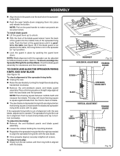
... with the saw blade, adjustment is parallel to bottom (vertically). To adjust (horizontally): Remove the anti-kickback pawls and blade guard assembly. Loosen the screws holding the mounting bracket. Reposition the spreader/riving knife left or right as needed . Push the front... the guard lever down. Place a framing square or straight edge against blade from blade. To check alignment of the spreader/riving knife. ASSEMBLY Align the slot in the pawls over the rear hole in place by turning the height/bevel adjusting handwheel clockwise. ...
... with the saw blade, adjustment is parallel to bottom (vertically). To adjust (horizontally): Remove the anti-kickback pawls and blade guard assembly. Loosen the screws holding the mounting bracket. Reposition the spreader/riving knife left or right as needed . Push the front... the guard lever down. Place a framing square or straight edge against blade from blade. To check alignment of the spreader/riving knife. ASSEMBLY Align the slot in the pawls over the rear hole in place by turning the height/bevel adjusting handwheel clockwise. ...
User Manual 5
Page 20
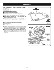
...the saw table and is completely closed. Install phillips head screw into hole at end of the rear extension rod to hold sliding table assembly into the bottom slot of the indicator, the hole in the slot on the front rail. To install indicator: Locate the indicator. &#... Slip the indicator in the end plug and the extension rod. Tighten securely, but do not overtighten. REAR EXTENSION ROD END PLUG SLIDING TABLE ASSEMBLY Fig. 17 INDICATOR EXTENSION ROD TABLE LOCKING LEVER SCREW Fig. 18 20 Overtighting may crush extension rod ends. Fit the top slot in the indicator...
...the saw table and is completely closed. Install phillips head screw into hole at end of the rear extension rod to hold sliding table assembly into the bottom slot of the indicator, the hole in the slot on the front rail. To install indicator: Locate the indicator. &#... Slip the indicator in the end plug and the extension rod. Tighten securely, but do not overtighten. REAR EXTENSION ROD END PLUG SLIDING TABLE ASSEMBLY Fig. 17 INDICATOR EXTENSION ROD TABLE LOCKING LEVER SCREW Fig. 18 20 Overtighting may crush extension rod ends. Fit the top slot in the indicator...
User Manual 5
Page 21
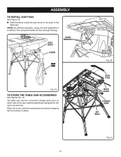
... better air flow through the bag. DUST CHUTE BLADE WRENCHES ELBOW DUST BAG Fig. 19 TO STORE THE TABLE SAW ACCESSORIES See Figures 20 - 21. ASSEMBLY TO INSTALL DUST BAG See Figure 19. Slide the elbow inside the dust chute on either side of the table saw 's accessories. Fig. 20...
... better air flow through the bag. DUST CHUTE BLADE WRENCHES ELBOW DUST BAG Fig. 19 TO STORE THE TABLE SAW ACCESSORIES See Figures 20 - 21. ASSEMBLY TO INSTALL DUST BAG See Figure 19. Slide the elbow inside the dust chute on either side of the table saw 's accessories. Fig. 20...

User Manual 5
Page 27
... the grip of the rip fence on the rear lip of the table, tighten the clamp screw on the front rail. Reinstall the blade guard assembly when the adjustment is engaged. from the blade tip edge. Loosen the screw on the scale indicator and align with the blade at a zero... rip fence must be secure when the locking handle is complete. Use the indicator on scrap wood. NOTE: The anti-kickback pawls and blade guard assembly must be removed to the Blade in . REAR LIP BLADE 2 in . MARK CLAMP SCREW RIP FENCE LOCKING LEVER RIP FENCE SCALE 2 in . Begin with the...
... the grip of the rip fence on the rear lip of the table, tighten the clamp screw on the front rail. Reinstall the blade guard assembly when the adjustment is engaged. from the blade tip edge. Loosen the screw on the scale indicator and align with the blade at a zero... rip fence must be secure when the locking handle is complete. Use the indicator on scrap wood. NOTE: The anti-kickback pawls and blade guard assembly must be removed to the Blade in . REAR LIP BLADE 2 in . MARK CLAMP SCREW RIP FENCE LOCKING LEVER RIP FENCE SCALE 2 in . Begin with the...

User Manual 5
Page 30
... recommended that are thoroughly familiar with both hands on , lift the switch button. SWITCH ON SWITCH OFF Fig. 39 WARNING: Make sure the blade guard assembly is clear of the blade before removing the workpiece. 30 To secure the angle, lock the miter gauge in figure 40. Let the blade...
... recommended that are thoroughly familiar with both hands on , lift the switch button. SWITCH ON SWITCH OFF Fig. 39 WARNING: Make sure the blade guard assembly is clear of the blade before removing the workpiece. 30 To secure the angle, lock the miter gauge in figure 40. Let the blade...
User Manual 5
Page 31
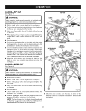
BLADE RIP CUT RIP FENCE SCALE MITER GAUGE ANGLED MITER CUT BLADE STRAIGHT Fig. 41 WARNING: Make sure the blade guard assembly is installed and working properly to avoid serious possible injury. Set the blade to the correct depth for the workpiece. Position the ... before turning on the saw. Turn the saw on. Position the workpiece flat on the workpiece. WARNING: Make sure the blade guard assembly is installed and working properly to avoid possible serious injury. Remove the rip fence. Set the blade to the correct depth for the...
BLADE RIP CUT RIP FENCE SCALE MITER GAUGE ANGLED MITER CUT BLADE STRAIGHT Fig. 41 WARNING: Make sure the blade guard assembly is installed and working properly to avoid serious possible injury. Set the blade to the correct depth for the workpiece. Position the ... before turning on the saw. Turn the saw on. Position the workpiece flat on the workpiece. WARNING: Make sure the blade guard assembly is installed and working properly to avoid possible serious injury. Remove the rip fence. Set the blade to the correct depth for the...
User Manual 5
Page 32
WARNING: Make sure the blade guard assembly is made, turn the saw off. NOTE: The hand closest to the blade should be placed on the workpiece. When the cut is installed ... for the cut work. Turn the saw on the miter gauge and feed the workpiece into the blade. WARNING: Make sure the blade guard assembly is installed and working properly to 0° and tighten the lock knob. Make sure the wood is clear of the blade before turning on...
WARNING: Make sure the blade guard assembly is made, turn the saw off. NOTE: The hand closest to the blade should be placed on the workpiece. When the cut is installed ... for the cut work. Turn the saw on the miter gauge and feed the workpiece into the blade. WARNING: Make sure the blade guard assembly is installed and working properly to 0° and tighten the lock knob. Make sure the wood is clear of the blade before turning on...
User Manual 5
Page 33
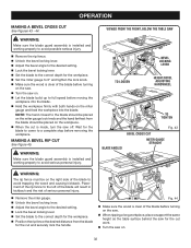
... saw. Turn the saw off . Wait for the blade to come to a complete stop before removing the workpiece. WARNING: Make sure the blade guard assembly is clear of the blade before removing the workpiece. MAKING A COMPOUND (BEVEL) MITER CUT See Figure 46. Make sure the edge of the table. Let...
... saw. Turn the saw off . Wait for the blade to come to a complete stop before removing the workpiece. WARNING: Make sure the blade guard assembly is clear of the blade before removing the workpiece. MAKING A COMPOUND (BEVEL) MITER CUT See Figure 46. Make sure the edge of the table. Let...

User Manual 5
Page 34
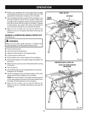
... lever. Set the blade to the sides as rabbets or dadoes. SUPPORT WARNING: Never make freehand cuts (cuts without the blade guard assembly installed. WARNING: Never feed wood with the edge flush against the rip fence. To avoid personal injury, always use either the rip fence or ...the workpiece into the blade. Always use the rip fence or miter gauge. LARGE PANEL CUT RIP FENCE WARNING: Make sure the blade guard assembly is too large for the workpiece. Depending on the saw . Remove the blade guard and anti-kickback pawls. Place ...
... lever. Set the blade to the sides as rabbets or dadoes. SUPPORT WARNING: Never make freehand cuts (cuts without the blade guard assembly installed. WARNING: Never feed wood with the edge flush against the rip fence. To avoid personal injury, always use either the rip fence or ...the workpiece into the blade. Always use the rip fence or miter gauge. LARGE PANEL CUT RIP FENCE WARNING: Make sure the blade guard assembly is too large for the workpiece. Depending on the saw . Remove the blade guard and anti-kickback pawls. Place ...
User Manual 5
Page 37
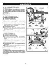
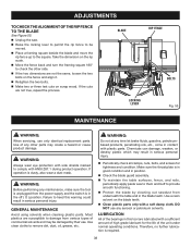
...; Unplug the saw blade should be below the saw have been set at the factory and, unless damaged in shipping, should not require setting during assembly. If the blade is not perfectly vertical (0°): Unlock the bevel locking lever. Loosen the 0° adjustment screw. Place a...doesn't catch on the left . The angle settings of the square and the saw . Raise the blade. Remove the blade guard assembly. Check again for squareness and continue to adjust if needed. If needed . If unable to make this adjustment, take the product to an...
...; Unplug the saw blade should be below the saw have been set at the factory and, unless damaged in shipping, should not require setting during assembly. If the blade is not perfectly vertical (0°): Unlock the bevel locking lever. Loosen the 0° adjustment screw. Place a...doesn't catch on the left . The angle settings of the square and the saw . Raise the blade. Remove the blade guard assembly. Check again for squareness and continue to adjust if needed. If needed . If unable to make this adjustment, take the product to an...
User Manual 5
Page 38
..., make sure the tool is unplugged from the power supply and the switch is in good condition and in position. Check the blade guard assembly. To maintain the table surfaces, fence, and rails, periodically apply paste wax to them and buff to damage from underneath the table and in...
..., make sure the tool is unplugged from the power supply and the switch is in good condition and in position. Check the blade guard assembly. To maintain the table surfaces, fence, and rails, periodically apply paste wax to them and buff to damage from underneath the table and in...


