
English Manual
Page 3
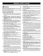
... accessories. DISCONNECT TOOLS. Be sure switch is in any other part that is damaged must be carefully checked to determine that keys and adjusting wrenches are intended for . It will draw. Make sure your extension cord is off when plugging in good condition. Also ...number, the heavier the cord. DRESS PROPERLY. A guard or other part that is damaged should be properly repaired or replaced by removing starter keys. DON'T FORCE TOOL. Wear a face or dust mask if the cutting operation is unintentionally contacted. KEEP WORK AREA CLEAN. ...
... accessories. DISCONNECT TOOLS. Be sure switch is in any other part that is damaged must be carefully checked to determine that keys and adjusting wrenches are intended for . It will draw. Make sure your extension cord is off when plugging in good condition. Also ...number, the heavier the cord. DRESS PROPERLY. A guard or other part that is damaged should be properly repaired or replaced by removing starter keys. DON'T FORCE TOOL. Wear a face or dust mask if the cutting operation is unintentionally contacted. KEEP WORK AREA CLEAN. ...

English Manual
Page 11
... and raise the blade for height adjustments or blade replacement. This saw is provided with optional clamps and accessories. Place the key in this handwheel to help prevent or reduce the possibility of the saw table, these table extension gives the operator additional support... others not qualified to -read scale provides precise measurements for through-sawing cuts. Kickback is a hazard in the OFF position, remove the switch key from the workpiece. BLADE - SLIDING TABLE EXTENSIONS - SPREADER - A metal piece of the blade guard assembly, slightly thinner than the speed of...
... and raise the blade for height adjustments or blade replacement. This saw is provided with optional clamps and accessories. Place the key in this handwheel to help prevent or reduce the possibility of the saw table, these table extension gives the operator additional support... others not qualified to -read scale provides precise measurements for through-sawing cuts. Kickback is a hazard in the OFF position, remove the switch key from the workpiece. BLADE - SLIDING TABLE EXTENSIONS - SPREADER - A metal piece of the blade guard assembly, slightly thinner than the speed of...
English Manual
Page 12
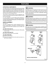
...miter cuts, bevel cuts, and compound cuts. TO TURN YOUR SAW OFF: Press the switch button down . Remove the switch key from accidentally starting , Always make sure your saw: Press the switch button down to position work for all through the table and is ...location. It is very important to turn the switch OFF ( O ) and remove the key. TO TURN YOUR SAW ON: With the switch key inserted into the power source. SWITCH ON SWITCH OFF SWITCH KEY SWITCH IN LOCKED POSITION 12 Fig. 3 Detailed instructions are provided in locking feature. TO lock...
...miter cuts, bevel cuts, and compound cuts. TO TURN YOUR SAW OFF: Press the switch button down . Remove the switch key from accidentally starting , Always make sure your saw: Press the switch button down to position work for all through the table and is ...location. It is very important to turn the switch OFF ( O ) and remove the key. TO TURN YOUR SAW ON: With the switch key inserted into the power source. SWITCH ON SWITCH OFF SWITCH KEY SWITCH IN LOCKED POSITION 12 Fig. 3 Detailed instructions are provided in locking feature. TO lock...

English Manual
Page 14
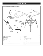
Quick Stand™ (leg stand 1 E. Hex Key 1 H. Extension Table (right 1 K. Screw (M4 x 10 mm 2 P. Blade Guard with your table saw: F A B C g h E N K I . Bevel Handle Assembly 1 Fig. 5 I O D J M P L A. Indicator (right 1 M. Rip Fence 1 D. Extension Table (left 1 O. Dust Bag 1 F. End Plug (left 1 J. End Plug (right 1 N. Screw (M4 x 25 mm 2 14 Blade Wrench 2 G. Indicator (left 1 L. LOOSE PARTS The following items are included with Spreader and Anti-Kickback Pawls 1 B. Miter Gauge 1 C.
Quick Stand™ (leg stand 1 E. Hex Key 1 H. Extension Table (right 1 K. Screw (M4 x 10 mm 2 P. Blade Guard with your table saw: F A B C g h E N K I . Bevel Handle Assembly 1 Fig. 5 I O D J M P L A. Indicator (right 1 M. Rip Fence 1 D. Extension Table (left 1 O. Dust Bag 1 F. End Plug (left 1 J. End Plug (right 1 N. Screw (M4 x 25 mm 2 14 Blade Wrench 2 G. Indicator (left 1 L. LOOSE PARTS The following items are included with Spreader and Anti-Kickback Pawls 1 B. Miter Gauge 1 C.

English Manual
Page 27
... make test cuts on scrap wood. Remove the rip fence by twisting the lock knob clockwise. NOTE: To prevent unauthorized use, remove the switch key as a cutoff gauge when cross cutting will result in the line of cut. Hold the workpiece firmly with the saw for the cut on...; Set the blade to the correct depth for the blade to come to a complete stop before removing the workpiece. 27 SWITCH ON SWITCH OFF SWITCH KEY SWITCH IN LOCKED POSITION Fig. 32 Fig. 33 Wait for the workpiece. Set the miter gauge to reduce the chance of this warning could...
... make test cuts on scrap wood. Remove the rip fence by twisting the lock knob clockwise. NOTE: To prevent unauthorized use, remove the switch key as a cutoff gauge when cross cutting will result in the line of cut. Hold the workpiece firmly with the saw for the cut on...; Set the blade to the correct depth for the blade to come to a complete stop before removing the workpiece. 27 SWITCH ON SWITCH OFF SWITCH KEY SWITCH IN LOCKED POSITION Fig. 32 Fig. 33 Wait for the workpiece. Set the miter gauge to reduce the chance of this warning could...

User Manual
Page 3
... manual for which it will cause a drop in line voltage resulting in good condition. TURN THE POWER OFF. Failure to see that keys and adjusting wrenches are rated for an extension cord 25 feet or less in use it for better and safer performance. Do not let ...your hand and frees both hands to rain. Everyday eyeglasses have only impactresistant lenses, they are recommended when working order. REMOVE ADJUSTING KEYS AND WRENCHES. A guard or other conditions that is damaged should wear safety glasses and be carefully checked to remove cut material when blade ...
... manual for which it will cause a drop in line voltage resulting in good condition. TURN THE POWER OFF. Failure to see that keys and adjusting wrenches are rated for an extension cord 25 feet or less in use it for better and safer performance. Do not let ...your hand and frees both hands to rain. Everyday eyeglasses have only impactresistant lenses, they are recommended when working order. REMOVE ADJUSTING KEYS AND WRENCHES. A guard or other conditions that is damaged should wear safety glasses and be carefully checked to remove cut material when blade ...

User Manual
Page 10
... the cabinet, locks the angle setting of the blade. Located on the front of the project you are locked with the locking handle. Place the key in this operator's manual as well as a knowledge of the cabinet shows the exact blade angle. BEVEL SCALE - The easy-to lower and raise the... KNOW YOUR TABLE SAW See Figure 2. The safe use the tool. 10 MITER GAUGE GROOVES - Kickback is a hazard in the OFF position, remove the switch key from the workpiece. A removable metal piece of the blade guard assembly, slightly thinner than the speed of the saw has an easy access power switch...
... the cabinet, locks the angle setting of the blade. Located on the front of the project you are locked with the locking handle. Place the key in this operator's manual as well as a knowledge of the cabinet shows the exact blade angle. BEVEL SCALE - The easy-to lower and raise the... KNOW YOUR TABLE SAW See Figure 2. The safe use the tool. 10 MITER GAUGE GROOVES - Kickback is a hazard in the OFF position, remove the switch key from the workpiece. A removable metal piece of the blade guard assembly, slightly thinner than the speed of the saw has an easy access power switch...

User Manual
Page 11
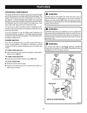
...children and others. This action will prevent the tool from the switch and store in serious personal injury. SWITCH ON SWITCH OFF SWITCH KEY SWITCH IN LOCKED POSITION 11 Fig. 3 FEATURES OPERATING COMPONENTS The upper portion of this warning may cause the workpiece to be kicked back... knife, anti-kickback pawls, and plastic blade guard. TO TURN YOUR SAW OFF: Press the switch down . Remove the switch key from accidentally starting , ALWAYS make sure your workpiece is set with a switch assembly that has a built-in contact with the blade before plugging tool ...
...children and others. This action will prevent the tool from the switch and store in serious personal injury. SWITCH ON SWITCH OFF SWITCH KEY SWITCH IN LOCKED POSITION 11 Fig. 3 FEATURES OPERATING COMPONENTS The upper portion of this warning may cause the workpiece to be kicked back... knife, anti-kickback pawls, and plastic blade guard. TO TURN YOUR SAW OFF: Press the switch down . Remove the switch key from accidentally starting , ALWAYS make sure your workpiece is set with a switch assembly that has a built-in contact with the blade before plugging tool ...

User Manual
Page 13
Anti-Kickback Pawls 1 B. Indicator 1 Fig. 5 I Q O J G A. Sliding Table Assembly 1 L. Miter Gauge 1 D. Blade Wrench 2 E. LOOSE PARTS The following items are included with your table saw: N K A C B H I D M F P E L I . Push Stick 1 H. Screw 2 J. Stand Legs 2 K. Leg Brace 2 P. Blade Guard 1 C. Switch Key 1 O. Handle Assembly 1 F. Lock Nut 8 13 Rip Fence 1 G. End Cap 1 M. Hex Key 1 N. Screw 8 Q.
Anti-Kickback Pawls 1 B. Indicator 1 Fig. 5 I Q O J G A. Sliding Table Assembly 1 L. Miter Gauge 1 D. Blade Wrench 2 E. LOOSE PARTS The following items are included with your table saw: N K A C B H I D M F P E L I . Push Stick 1 H. Screw 2 J. Stand Legs 2 K. Leg Brace 2 P. Blade Guard 1 C. Switch Key 1 O. Handle Assembly 1 F. Lock Nut 8 13 Rip Fence 1 G. End Cap 1 M. Hex Key 1 N. Screw 8 Q.

User Manual
Page 29
...wood first. Use the miter gauge when making cross, miter, bevel, and compound miter cuts. NOTE: To prevent unauthorized use, remove the switch key as a cutoff gauge when cross cutting will result in this manual. Wait for ripping and cross cut is a high-quality combination blade suitable for...turning on the saw usage and specialized woodworking procedures for the workpiece. Set the miter gauge to be placed on table saw . SWITCH KEY Remove the rip fence. Set the blade to the correct depth for your reference. The blade provided with both hands on ...
...wood first. Use the miter gauge when making cross, miter, bevel, and compound miter cuts. NOTE: To prevent unauthorized use, remove the switch key as a cutoff gauge when cross cutting will result in this manual. Wait for ripping and cross cut is a high-quality combination blade suitable for...turning on the saw usage and specialized woodworking procedures for the workpiece. Set the miter gauge to be placed on table saw . SWITCH KEY Remove the rip fence. Set the blade to the correct depth for your reference. The blade provided with both hands on ...
User Manual 4
Page 3
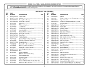
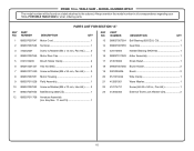
RYOBI 10 in ., Pan Hd 8 41 080015001436 Screw (M6 x 18 mm 3 15 0121010237 End Cap, Extension Table Rod 1 42 080015001603 Hex Nut (1/4-20 2 16 089037011006 Scale ... 1 54 089037011048 Washer (D6.5 x D20 x 2.5t 2 55 089110101066 Screw w/Washer (M4 x 12 mm, Pan Hd.)......... 1 3 NUMBER DESCRIPTION PARTS LIST FOR FIGURE A KEY PART QTY NO. KEY PART NO. MODEL NUMBER RTS21 The model number will be found on a label attached to the cabinet. Always mention the model number in all correspondence regarding your...
RYOBI 10 in ., Pan Hd 8 41 080015001436 Screw (M6 x 18 mm 3 15 0121010237 End Cap, Extension Table Rod 1 42 080015001603 Hex Nut (1/4-20 2 16 089037011006 Scale ... 1 54 089037011048 Washer (D6.5 x D20 x 2.5t 2 55 089110101066 Screw w/Washer (M4 x 12 mm, Pan Hd.)......... 1 3 NUMBER DESCRIPTION PARTS LIST FOR FIGURE A KEY PART QTY NO. KEY PART NO. MODEL NUMBER RTS21 The model number will be found on a label attached to the cabinet. Always mention the model number in all correspondence regarding your...

User Manual 4
Page 4
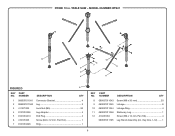
TABLE SAW - Hd 2 Motor Assembly 1 Washer (D1/4 in . RYOBI 10 in . Key Nos. 95-100 1 Anti-Kickback Pawls Assembly 1 Rear Support 1 Rear Rod 2 Extension Table 1 Saw Table 1 Outfeed Support Bracket 2 Rip Fence Assembly (See Figure C 1...Hands Warning Label 2 Guard Warning Label (Left 1 Guard Warning Label (Right 1 Warning Label (Upper Barrier 1 Dado Throat Plate (Optional 1 Operator's Manual (089037011908) 4 MODEL NUMBER RTS21 The model number will be found on a label attached to the cabinet. Always mention the model number in all correspondence regarding your 10 in ., Pan...
TABLE SAW - Hd 2 Motor Assembly 1 Washer (D1/4 in . RYOBI 10 in . Key Nos. 95-100 1 Anti-Kickback Pawls Assembly 1 Rear Support 1 Rear Rod 2 Extension Table 1 Saw Table 1 Outfeed Support Bracket 2 Rip Fence Assembly (See Figure C 1...Hands Warning Label 2 Guard Warning Label (Left 1 Guard Warning Label (Right 1 Warning Label (Upper Barrier 1 Dado Throat Plate (Optional 1 Operator's Manual (089037011908) 4 MODEL NUMBER RTS21 The model number will be found on a label attached to the cabinet. Always mention the model number in all correspondence regarding your 10 in ., Pan...
User Manual 4
Page 6
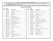
RYOBI 10 in . PORTABLE TABLE SAW or when ordering parts. NUMBER DESCRIPTION QTY 1 410031710 2 0134010238 3 0101010312 4 0101010313 5 0131020211 6 089037011706 7 080015001473 8 089037011011 9 089037011901 10 080015001475 ... 089037011008 089037011904 0121015002 412011109 416090001 089037011707 089037011025 411072702 412012041 0131020212 0101140203 Switch Assembly (Inc. MODEL NUMBER RTS21 The model number will be found on a label attached to the cabinet. PARTS LIST FOR FIGURE B KEY PART NO. Key No. 22 1 Plate 1 Screw (M4 x 16 mm, Pan Hd 2 Cord Clamp 1 Warning Label (French 1...
RYOBI 10 in . PORTABLE TABLE SAW or when ordering parts. NUMBER DESCRIPTION QTY 1 410031710 2 0134010238 3 0101010312 4 0101010313 5 0131020211 6 089037011706 7 080015001473 8 089037011011 9 089037011901 10 080015001475 ... 089037011008 089037011904 0121015002 412011109 416090001 089037011707 089037011025 411072702 412012041 0131020212 0101140203 Switch Assembly (Inc. MODEL NUMBER RTS21 The model number will be found on a label attached to the cabinet. PARTS LIST FOR FIGURE B KEY PART NO. Key No. 22 1 Plate 1 Screw (M4 x 16 mm, Pan Hd 2 Cord Clamp 1 Warning Label (French 1...

User Manual 4
Page 7
RYOBI 10 in. NUMBER DESCRIPTION QTY 1 411071001 Lock Nut (M6 1 11 089037011035 Front Block 1 2 412011030 Washer (D6.5 x D16 x 1.5t 3 12 089037011036 Rod 1 3 089037011032 Rear Clamping Plate 1 ... (8-32 x 8.5 mm, Flat Hd 2 9 410541003 Screw (M4 x 10 mm, Pan Hd 1 19 412011712 Washer (D1/4 x D13 x 1.5t 1 10 089037011034 Indicator 1 089037011704 Rip Fence Assembly (Inc. Key Nos. 1-18)........ 1 7 TABLE SAW - NUMBER DESCRIPTION QTY KEY PART NO. MODEL NUMBER RTS21 1 2 3 4 19 6 7 2 9 16 10 11 12 17 18 5 8 FIGURE C 13 14 15...
RYOBI 10 in. NUMBER DESCRIPTION QTY 1 411071001 Lock Nut (M6 1 11 089037011035 Front Block 1 2 412011030 Washer (D6.5 x D16 x 1.5t 3 12 089037011036 Rod 1 3 089037011032 Rear Clamping Plate 1 ... (8-32 x 8.5 mm, Flat Hd 2 9 410541003 Screw (M4 x 10 mm, Pan Hd 1 19 412011712 Washer (D1/4 x D13 x 1.5t 1 10 089037011034 Indicator 1 089037011704 Rip Fence Assembly (Inc. Key Nos. 1-18)........ 1 7 TABLE SAW - NUMBER DESCRIPTION QTY KEY PART NO. MODEL NUMBER RTS21 1 2 3 4 19 6 7 2 9 16 10 11 12 17 18 5 8 FIGURE C 13 14 15...
User Manual 4
Page 8
... End Plug 4 12 410451016 Screw (M6 x 12 mm, Pan Hd 4 6 410191003 Screw (M4 x 12 mm, Pan Hd 1 089037011705 Leg Stand Assembly (Inc. NUMBER DESCRIPTION QTY KEY PART NO. RYOBI 10 in. Key Nos. 1-12)........ 1 7 0121010228 Ring 1 8 TABLE SAW - MODEL NUMBER RTS21 12 11 1 10 6 7 9 2 3 4 8 FIGURE...
... End Plug 4 12 410451016 Screw (M6 x 12 mm, Pan Hd 4 6 410191003 Screw (M4 x 12 mm, Pan Hd 1 089037011705 Leg Stand Assembly (Inc. NUMBER DESCRIPTION QTY KEY PART NO. RYOBI 10 in. Key Nos. 1-12)........ 1 7 0121010228 Ring 1 8 TABLE SAW - MODEL NUMBER RTS21 12 11 1 10 6 7 9 2 3 4 8 FIGURE...
User Manual 4
Page 10
MODEL NUMBER RTS21 The model number will be found on a label attached to the cabinet. Always mention the model number in all correspondence regarding your 10 in ., Pan Hd 1 412042002 External Tooth Lock Washer (D4 2 10 PARTS LIST FOR SECTION "A" KEY PART NO. Key Nos 11 and 13 1 KEY NO. 13 14... Motor Housing 1 9 089037011028 Field Assembly 1 10 089037007052 Screw w/Washer (M5 x 70 mm, Hex Hd.)......... 2 11 089037007053 Ball Bearing (6001ZZ 1 12 089037011708 Armature Assembly (Inc. RYOBI 10 in. TABLE SAW - PORTABLE TABLE SAW or when ordering parts.
MODEL NUMBER RTS21 The model number will be found on a label attached to the cabinet. Always mention the model number in all correspondence regarding your 10 in ., Pan Hd 1 412042002 External Tooth Lock Washer (D4 2 10 PARTS LIST FOR SECTION "A" KEY PART NO. Key Nos 11 and 13 1 KEY NO. 13 14... Motor Housing 1 9 089037011028 Field Assembly 1 10 089037007052 Screw w/Washer (M5 x 70 mm, Hex Hd.)......... 2 11 089037007053 Ball Bearing (6001ZZ 1 12 089037011708 Armature Assembly (Inc. RYOBI 10 in. TABLE SAW - PORTABLE TABLE SAW or when ordering parts.
User Manual 5
Page 3
...performance. Never yank cord to avoid risk of power and overheating. These cords are recommended when working order. REMOVE ADJUSTING KEYS AND WRENCHES. Everyday eyeglasses have only impactresistant lenses, they are removed from work into moving . 3 Consult the operator's manual for..., ranges, refrigerator enclosures. KEEP GUARDS IN PLACE and in doubt, use of the tool, a guard or other part that keys and adjusting wrenches are NOT safety glasses. SECURE WORK. GENERAL SAFETY RULES WARNING: Read and understand all times. MAINTAIN...
...performance. Never yank cord to avoid risk of power and overheating. These cords are recommended when working order. REMOVE ADJUSTING KEYS AND WRENCHES. Everyday eyeglasses have only impactresistant lenses, they are removed from work into moving . 3 Consult the operator's manual for..., ranges, refrigerator enclosures. KEEP GUARDS IN PLACE and in doubt, use of the tool, a guard or other part that keys and adjusting wrenches are NOT safety glasses. SECURE WORK. GENERAL SAFETY RULES WARNING: Read and understand all times. MAINTAIN...

User Manual 5
Page 11
... the wood to -read scale provides precise measurements for a miter cut . Failure to heed this warning could result in the OFF position, remove the switch key from the workpiece. This lever, placed just under the saw table, this product, familiarize yourself with all operating features and safety rules. OUTFEED SUPPORT - BLADE... cut . The miter gauge aligns the wood for bevel angles easy. The miter gauge rides in a location that is below the front rail. Place the key in the grooves on the front of this product requires an understanding of the blade.
... the wood to -read scale provides precise measurements for a miter cut . Failure to heed this warning could result in the OFF position, remove the switch key from the workpiece. This lever, placed just under the saw table, this product, familiarize yourself with all operating features and safety rules. OUTFEED SUPPORT - BLADE... cut . The miter gauge aligns the wood for bevel angles easy. The miter gauge rides in a location that is below the front rail. Place the key in the grooves on the front of this product requires an understanding of the blade.
User Manual 5
Page 12
...guard assembly includes: riving knife/spreader/splitter, anti-kickback pawls, and plastic blade guard. TO TURN YOUR SAW ON: With the switch key inserted into the power source. A scale on the front of the cabinet. This saw is set with the blade before plugging tool into the ..., miter cuts, bevel cuts, and compound cuts. TO TURN YOUR SAW OFF: Press the switch down . Remove the switch key from accidentally starting , ALWAYS make sure your workpiece is in serious personal injury. The height of the blade is equipped with a switch assembly that has...
...guard assembly includes: riving knife/spreader/splitter, anti-kickback pawls, and plastic blade guard. TO TURN YOUR SAW ON: With the switch key inserted into the power source. A scale on the front of the cabinet. This saw is set with the blade before plugging tool into the ..., miter cuts, bevel cuts, and compound cuts. TO TURN YOUR SAW OFF: Press the switch down . Remove the switch key from accidentally starting , ALWAYS make sure your workpiece is in serious personal injury. The height of the blade is equipped with a switch assembly that has...
User Manual 5
Page 14
Blade Wrench 2 E. Push Stick 1 Fig. 5 H. Dust Bag 1 M. Hex Key (3 mm, 5 mm 2 N. Screw 2 J. End Cap 1 14 Rip Fence 1 G. Quick Stand™ (Leg Stand 1 K. Sliding Table Assembly 1 L. Switch Key 1 O. Miter Gauge 1 D. Indicator 1 I C E F D J M G A. Handle Assembly 1 F. Anti-Kickback Pawls 1 B. Blade Guard 1 C. LOOSE PARTS The following items are included with your table saw: A L K N B I H O I .
Blade Wrench 2 E. Push Stick 1 Fig. 5 H. Dust Bag 1 M. Hex Key (3 mm, 5 mm 2 N. Screw 2 J. End Cap 1 14 Rip Fence 1 G. Quick Stand™ (Leg Stand 1 K. Sliding Table Assembly 1 L. Switch Key 1 O. Miter Gauge 1 D. Indicator 1 I C E F D J M G A. Handle Assembly 1 F. Anti-Kickback Pawls 1 B. Blade Guard 1 C. LOOSE PARTS The following items are included with your table saw: A L K N B I H O I .


