
English Manual
Page 1
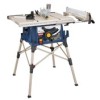
OPERATOR'S MANUAL 10 in. WARNING: To reduce the risk of rugged, trouble-free performance. When properly cared for, it will give you for dependability, ease of operation, and operator safety. Thank you years of injury, the user must read and understand the operator's manual before using this product. SAVE THIS MANUAL FOR FUTURE REFERENCE Table Saw BTS16 Your table saw has been engineered and manufactured to our high standard for your purchase.
OPERATOR'S MANUAL 10 in. WARNING: To reduce the risk of rugged, trouble-free performance. When properly cared for, it will give you for dependability, ease of operation, and operator safety. Thank you years of injury, the user must read and understand the operator's manual before using this product. SAVE THIS MANUAL FOR FUTURE REFERENCE Table Saw BTS16 Your table saw has been engineered and manufactured to our high standard for your purchase.

English Manual
Page 3
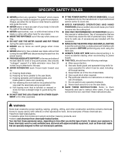
Learn the saw while it was designed. USE RIGHT TOOL. Form habit of power and overheating. Follow instructions for better and safer performance. Cluttered areas and benches ... next heavier gauge. Don't force the tool or attachment to do the job better and safer at the feed rate for which it on the saw 's applications and limitations as well as the specific potential hazards related to this tool. GUARD AGAINST ELECTRICAL SHOCK by preventing body contact with padlocks...
Learn the saw while it was designed. USE RIGHT TOOL. Form habit of power and overheating. Follow instructions for better and safer performance. Cluttered areas and benches ... next heavier gauge. Don't force the tool or attachment to do the job better and safer at the feed rate for which it on the saw 's applications and limitations as well as the specific potential hazards related to this tool. GUARD AGAINST ELECTRICAL SHOCK by preventing body contact with padlocks...

English Manual
Page 4
... at an authorized service facility. Stay out of the motor could ignite fumes. Inspect TOOL CORDS periodically. Through-sawing operations are included with saw . A push stick is properly grounded. Use only correct electrical devices: 3-wire extension cords that are secure.... 3-pole receptacles that are tired. Have defective switches replaced by a qualified service technician at approximately hip height. NEVER OPERATE THE SAW ON THE FLOOR. GUARD AGAINST KICKBACK. Never use . NEVER START A TOOL WHEN ANY ROTATiNG COMPONENT IS IN CONTACT...
... at an authorized service facility. Stay out of the motor could ignite fumes. Inspect TOOL CORDS periodically. Through-sawing operations are included with saw . A push stick is properly grounded. Use only correct electrical devices: 3-wire extension cords that are secure.... 3-pole receptacles that are tired. Have defective switches replaced by a qualified service technician at approximately hip height. NEVER OPERATE THE SAW ON THE FLOOR. GUARD AGAINST KICKBACK. Never use . NEVER START A TOOL WHEN ANY ROTATiNG COMPONENT IS IN CONTACT...
English Manual
Page 5
... lighting to power supply. THIS TOOL should have a straight edge to instructions on how often you ) by power sanding, sawing, grinding, drilling, and other construction activities contains chemicals known to these instructions also. c) Keeping spreader, anti-kickback pawls, and blade... for other masonry products, and • arsenic and chromium from these chemicals are specially designed to instruct other reproductive harm. b) Use saw . AVOID KICKBACKS (work that are : • lead from lead-based paints, • crystalline silica from bricks and cement...
... lighting to power supply. THIS TOOL should have a straight edge to instructions on how often you ) by power sanding, sawing, grinding, drilling, and other construction activities contains chemicals known to these instructions also. c) Keeping spreader, anti-kickback pawls, and blade... for other masonry products, and • arsenic and chromium from these chemicals are specially designed to instruct other reproductive harm. b) Use saw . AVOID KICKBACKS (work that are : • lead from lead-based paints, • crystalline silica from bricks and cement...

English Manual
Page 8
... and the motor will not get caught on the cord's jacket. It should be plugged into an outlet, double check the power supply. If the saw does not operate when plugged into a matching outlet that the tool will cause a drop in line voltage, resulting in figure 1. Grounding Pin 120 V Grounded outlet...
... and the motor will not get caught on the cord's jacket. It should be plugged into an outlet, double check the power supply. If the saw does not operate when plugged into a matching outlet that the tool will cause a drop in line voltage, resulting in figure 1. Grounding Pin 120 V Grounded outlet...
English Manual
Page 9
...contact with the workpiece at any angle other than 90°. Revolutions Per Minute (RPM) The number of the workpiece. Through Sawing Any cutting operation where the blade extends completely through the thickness of the blade to reduce the thickness of the workpiece. Worktable Surface... FPM or SPM Feet per minute (or strokes per minute), used for drilling large holes accurately. Resaw A cutting operation to the fence. Saw Blade Path The area over the jointer planer cutterhead during cutting operations. Freehand Performing a cut by a spinning object in the workpiece (requires...
...contact with the workpiece at any angle other than 90°. Revolutions Per Minute (RPM) The number of the workpiece. Through Sawing Any cutting operation where the blade extends completely through the thickness of the blade to reduce the thickness of the workpiece. Worktable Surface... FPM or SPM Feet per minute (or strokes per minute), used for drilling large holes accurately. Resaw A cutting operation to the fence. Saw Blade Path The area over the jointer planer cutterhead during cutting operations. Freehand Performing a cut by a spinning object in the workpiece (requires...

English Manual
Page 11
... toward the operator, the teeth dig into the wood to -read indicator shows the exact angle for height adjustments or blade replacement. This saw blade for rip cuts. If the workpiece should be pulled back toward the operator. Failure to -read scale on each side of the... the switch. SPREADER - The teeth on the front rail, the easy-to heed this handwheel to -read scale provides precise measurements for through-sawing cuts. Always keep the kerf open and prevent kickback. HEIGHT/BEVEL ADJUSTING HANDWHEEL - Kickback is raised and lowered with the locking handle. This...
... toward the operator, the teeth dig into the wood to -read indicator shows the exact angle for height adjustments or blade replacement. This saw blade for rip cuts. If the workpiece should be pulled back toward the operator. Failure to -read scale on each side of the... the switch. SPREADER - The teeth on the front rail, the easy-to heed this handwheel to -read scale provides precise measurements for through-sawing cuts. Always keep the kerf open and prevent kickback. HEIGHT/BEVEL ADJUSTING HANDWHEEL - Kickback is raised and lowered with the locking handle. This...
English Manual
Page 12
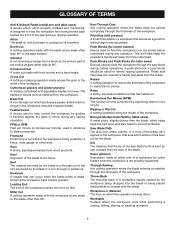
... cabinet. This feature is intended to prevent unauthorized and possible hazardous use by an insert called the throat plate. TO TURN YOUR SAW ON: With the switch key inserted into the power source. SWITCH ON SWITCH OFF SWITCH KEY SWITCH IN LOCKED POSITION 12 Fig...: riving knife/spreader/splitter, anti-kickback pawls, and plastic blade guard. FEATURES Operating Components The upper portion of the blade projects up through -sawing operations. The rip fence is surrounded by children and others. The height of the blade is very important to turn ON ( l ). It...
... cabinet. This feature is intended to prevent unauthorized and possible hazardous use by an insert called the throat plate. TO TURN YOUR SAW ON: With the switch key inserted into the power source. SWITCH ON SWITCH OFF SWITCH KEY SWITCH IN LOCKED POSITION 12 Fig...: riving knife/spreader/splitter, anti-kickback pawls, and plastic blade guard. FEATURES Operating Components The upper portion of the blade projects up through -sawing operations. The rip fence is surrounded by children and others. The height of the blade is very important to turn ON ( l ). It...

English Manual
Page 13
FEATURES BLADES For maximum performance, it is recommended that you with your saw. Failure to heed this tool. Wrench Fig. 4 13 WARNING: Do not use the 24-tooth, 10 in . TOOLS NEEDED The following tools (not included) are ...
FEATURES BLADES For maximum performance, it is recommended that you with your saw. Failure to heed this tool. Wrench Fig. 4 13 WARNING: Do not use the 24-tooth, 10 in . TOOLS NEEDED The following tools (not included) are ...

English Manual
Page 14
Dust Bag 1 F. Screw (M4 x 25 mm 2 14 Miter Gauge 1 C. Hex Key 1 H. Screw (M4 x 10 mm 2 P. Rip Fence 1 D. Extension Table (right 1 K. Indicator (left 1 O. Indicator (right 1 M. End Plug (left 1 L. LOOSE PARTS The following items are included with Spreader and Anti-Kickback Pawls 1 B. Blade Guard with your table saw: F A B C g h E N K I . Bevel Handle Assembly 1 Fig. 5 I O D J M P L A. Quick Stand™ (leg stand 1 E. End Plug (right 1 N. Blade Wrench 2 G. Extension Table (left 1 J.
Dust Bag 1 F. Screw (M4 x 25 mm 2 14 Miter Gauge 1 C. Hex Key 1 H. Screw (M4 x 10 mm 2 P. Rip Fence 1 D. Extension Table (right 1 K. Indicator (left 1 O. Indicator (right 1 M. End Plug (left 1 L. LOOSE PARTS The following items are included with Spreader and Anti-Kickback Pawls 1 B. Blade Guard with your table saw: F A B C g h E N K I . Bevel Handle Assembly 1 Fig. 5 I O D J M P L A. Quick Stand™ (leg stand 1 E. End Plug (right 1 N. Blade Wrench 2 G. Extension Table (left 1 J.
English Manual
Page 15
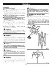
... for use this tool. warning: Do not attempt to do not operate this tool until the missing parts are replaced. WARNING: Do not lift the saw on the floor. Ignoring these precautions can result in line with your legs, not your back. Fig. 6 warning: Never stand directly in serious personal ... this leg stand with other equipment or for other purposes. Remove the Quick Stand™ from leg stand storage in the back of the saw by separating the hook and loop straps. Place the Quick Stand™ on a level work surface. NOTE: This tool is complete. If shipping ...
... for use this tool. warning: Do not attempt to do not operate this tool until the missing parts are replaced. WARNING: Do not lift the saw on the floor. Ignoring these precautions can result in line with your legs, not your back. Fig. 6 warning: Never stand directly in serious personal ... this leg stand with other equipment or for other purposes. Remove the Quick Stand™ from leg stand storage in the back of the saw by separating the hook and loop straps. Place the Quick Stand™ on a level work surface. NOTE: This tool is complete. If shipping ...
English Manual
Page 16
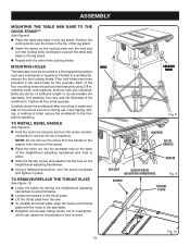
... four mounting holes should be of the workbench. NOTE: Do not remove the screw from the handle or the washer from the saw must be bolted securely using 3/8 in the saw base on the leg stand. to remove/replace the THROAT PLATE See Figure 10. Lower the blade by turning the... nuts (not included). To install BEVEL HANDLE See Figure 9. Hold the nylon nut securely and turn the locking knob clockwise to secure the table saw base to the leg stand. Repeat with the holes in place. Slide the handle, screw, and washer into the hole on the locking...
... four mounting holes should be of the workbench. NOTE: Do not remove the screw from the handle or the washer from the saw must be bolted securely using 3/8 in the saw base on the leg stand. to remove/replace the THROAT PLATE See Figure 10. Lower the blade by turning the... nuts (not included). To install BEVEL HANDLE See Figure 9. Hold the nylon nut securely and turn the locking knob clockwise to secure the table saw base to the leg stand. Repeat with the holes in place. Slide the handle, screw, and washer into the hole on the locking...

English Manual
Page 17
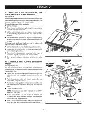
...blade rotation. NOTE: Arbor shaft has right hand threads. Reinstall the throat plate. ASSEMBLY to : To Check, and Align the Spreader, Saw Blade, and Blade Guard Assembly. Hang the bag by turning the height/bevel adjusting handwheel clockwise. NOTE: For efficient operation, empty the dust bag ... the spreader to its full height by hooking the bag onto the hangers on the arbor shaft. Insert the closed end of the saw . Lower the blade by turning the height/bevel adjusting handwheel counterclockwise. Remove the wing screw and washer from beneath the...
...blade rotation. NOTE: Arbor shaft has right hand threads. Reinstall the throat plate. ASSEMBLY to : To Check, and Align the Spreader, Saw Blade, and Blade Guard Assembly. Hang the bag by turning the height/bevel adjusting handwheel clockwise. NOTE: For efficient operation, empty the dust bag ... the spreader to its full height by hooking the bag onto the hangers on the arbor shaft. Insert the closed end of the saw . Lower the blade by turning the height/bevel adjusting handwheel counterclockwise. Remove the wing screw and washer from beneath the...
English Manual
Page 18
... Fig. 14 EXTENSION ROD END PLUG INDICATOR (lF) Fig. 15 To adjust: Unplug the saw table and is out of the spreader: Unplug the saw. Raise the saw blade by turning the height/bevel adjusting handwheel counterclockwise. Lift the anti-kickback pawls and place ...a framing square or straight edge against the saw then raise the blade guard assembly. Loosen the wing nut holding the blade guard assembly to the mounting bracket. ...
... Fig. 14 EXTENSION ROD END PLUG INDICATOR (lF) Fig. 15 To adjust: Unplug the saw table and is out of the spreader: Unplug the saw. Raise the saw blade by turning the height/bevel adjusting handwheel counterclockwise. Lift the anti-kickback pawls and place ...a framing square or straight edge against the saw then raise the blade guard assembly. Loosen the wing nut holding the blade guard assembly to the mounting bracket. ...
English Manual
Page 19
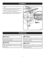
... the illustrations in the rear extension rod and tighten. Open the extension table completely. Repeat the above steps for clarity, do not operate the saw without the blade guard unless specifically instructed to do so could result in objects being thrown into your eyes in possible serious injury. When the...
... the illustrations in the rear extension rod and tighten. Open the extension table completely. Repeat the above steps for clarity, do not operate the saw without the blade guard unless specifically instructed to do so could result in objects being thrown into your eyes in possible serious injury. When the...

English Manual
Page 20
...61550; To avoid pinching the blade, support the work for a grip on non-through the blade. cutting aids See Figure 17. Never saw Failing to all local codes and ordinances. OPERATION APPLICATIONS You may be jerked loose from the underside. Basic Operation of the ...Cabinet making a cut with a 90˚ notch in a specific project. Kickback can be narrower than the workpiece, with incorrect blade depth Sawing into a loose knot or nail. Always use the anti-kickback pawls Cutting with the blade. Use the right type...
...61550; To avoid pinching the blade, support the work for a grip on non-through the blade. cutting aids See Figure 17. Never saw Failing to all local codes and ordinances. OPERATION APPLICATIONS You may be jerked loose from the underside. Basic Operation of the ...Cabinet making a cut with a 90˚ notch in a specific project. Kickback can be narrower than the workpiece, with incorrect blade depth Sawing into a loose knot or nail. Always use the anti-kickback pawls Cutting with the blade. Use the right type...

English Manual
Page 21
... cuts are non-through cuts which can be on the waste side of the workpiece. Cross Cut WARNING: Always make sure one side of the saw. The wood is vertical. The blade is fed into the cut at any angle to finish the cut when ripping a long narrow piece of cut...
... cuts are non-through cuts which can be on the waste side of the workpiece. Cross Cut WARNING: Always make sure one side of the saw. The wood is vertical. The blade is fed into the cut at any angle to finish the cut when ripping a long narrow piece of cut...

English Manual
Page 22
...., 8 in., 10 in., and 12 in. warning: Do not locate the featherboard to the rear of the workpiece to the edge of the saw blade area. Place the workpiece against the uncut portion of the workpiece. Attach a C-clamp to secure the featherboard to avoid kickback that could cause ... fence and cut in the stock. spaces between the fingers. Mark the board from the featherboard pinching the workpiece and binding the blade in the saw kerf. fingers and 1/8 in . HOW TO MOUNT A FEATHERBOARD See Figure 20. operation FEATHERBOARD A featherboard is a device used to heed this warning ...
...., 8 in., 10 in., and 12 in. warning: Do not locate the featherboard to the rear of the workpiece to the edge of the saw blade area. Place the workpiece against the uncut portion of the workpiece. Attach a C-clamp to secure the featherboard to avoid kickback that could cause ... fence and cut in the stock. spaces between the fingers. Mark the board from the featherboard pinching the workpiece and binding the blade in the saw kerf. fingers and 1/8 in . HOW TO MOUNT A FEATHERBOARD See Figure 20. operation FEATHERBOARD A featherboard is a device used to heed this warning ...

English Manual
Page 23
... or lower it closer to 1/4 in . TO CHANGE BLADE ANGLE See Figure 22. to 45°. If the bevel indicator is at zero when the saw then turning it. Retighten the screw. operation TO CHANGE BLADE DEPTH See Figure 21. Note: A 90° cut has a 0° bevel and a 45° cut... control by pushing the bevel lock lever all the way to the right. Adjust the bevel angle by pushing the wheel in toward the saw blade is not at 90°, adjust the indicator by loosening the screw and setting it clockwise decreases the angle, bringing the blade closer to...
... or lower it closer to 1/4 in . TO CHANGE BLADE ANGLE See Figure 22. to 45°. If the bevel indicator is at zero when the saw then turning it. Retighten the screw. operation TO CHANGE BLADE DEPTH See Figure 21. Note: A 90° cut has a 0° bevel and a 45° cut... control by pushing the bevel lock lever all the way to the right. Adjust the bevel angle by pushing the wheel in toward the saw blade is not at 90°, adjust the indicator by loosening the screw and setting it clockwise decreases the angle, bringing the blade closer to...
English Manual
Page 24
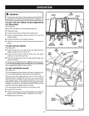
...the front rail. Push the locking lever down to automatically align and secure the fence. mark SAW TABLE rip fence Front rail Locking lever Fig. 24 locking lever REAR LIP MITER GAUGE Fig. 25 ...KNOB Fig. 26 24 Begin with the blade at a zero angle (straight up). Unplug the saw table and pull slightly toward the front of the unit. Lower the front end of the rip... action. TO use the Rip Fence See Figure 25. Place the rear lip on the rear of the saw . Loosen the rip fence by lifting the locking lever. Using a framing square, set the rip...
...the front rail. Push the locking lever down to automatically align and secure the fence. mark SAW TABLE rip fence Front rail Locking lever Fig. 24 locking lever REAR LIP MITER GAUGE Fig. 25 ...KNOB Fig. 26 24 Begin with the blade at a zero angle (straight up). Unplug the saw table and pull slightly toward the front of the unit. Lower the front end of the rip... action. TO use the Rip Fence See Figure 25. Place the rear lip on the rear of the saw . Loosen the rip fence by lifting the locking lever. Using a framing square, set the rip...


