
English Manual
Page 4
...operations. Normal sparking of any other moving . Blade coasts after being turned off immediately if blade binds or stalls. USE RIP FENCE. Have defective switches replaced by a qualified electrician. Keep TOOL dry, clean, and free from the rotating blade. Inspect EXTENSION ...USE IN AN EXPLOSIVE ATMOSPHERE. GENERAL SAFETY RULES work or around or over the blade. ALWAYS SECURE work firmly against the rip fence or miter gauge. SPECIFIC SAFETY RULES FIRMLY BOLT THE SAW TO A WORK BENCH OR LEG STAND at an authorized service facility....
...operations. Normal sparking of any other moving . Blade coasts after being turned off immediately if blade binds or stalls. USE RIP FENCE. Have defective switches replaced by a qualified electrician. Keep TOOL dry, clean, and free from the rotating blade. Inspect EXTENSION ...USE IN AN EXPLOSIVE ATMOSPHERE. GENERAL SAFETY RULES work or around or over the blade. ALWAYS SECURE work firmly against the rip fence or miter gauge. SPECIFIC SAFETY RULES FIRMLY BOLT THE SAW TO A WORK BENCH OR LEG STAND at an authorized service facility....
English Manual
Page 5
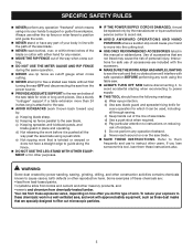
..., depending on reducing risk of kickback. SPECIFIC SAFETY RULES NEVER perform any operation "freehand" which it is attached to guide along the fence. DO NOT USE THE LEG STAND WITH OTHER EQUIPMENT or for other masonry products, and • arsenic and chromium from chemically-treated ...disconnecting the saw blade. g) Never reach around or over , or within three inches of the blade or cutter with either the rip fence or miter fence to power supply. THIS TOOL should have any part of personal injury. Your risk from these chemicals: work in place and ...
..., depending on reducing risk of kickback. SPECIFIC SAFETY RULES NEVER perform any operation "freehand" which it is attached to guide along the fence. DO NOT USE THE LEG STAND WITH OTHER EQUIPMENT or for other masonry products, and • arsenic and chromium from chemically-treated ...disconnecting the saw blade. g) Never reach around or over , or within three inches of the blade or cutter with either the rip fence or miter fence to power supply. THIS TOOL should have any part of personal injury. Your risk from these chemicals: work in place and ...
English Manual
Page 9
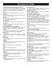
...to help keep the operator's hands well away from the workpiece. Kerf The material removed by the blade in front of the blade to the fence. Non-Through Cuts Any cutting operation where the blade does not extend completely through the saw during cutting operations. Saw Blade Path The area ...Pilot Hole (drill presses) A small hole drilled in reference to feed the workpiece over , under, behind, or in a through cut or the slot produced by a fence, miter gauge, or other aids. A push stick (not a push block) should be or has been cut removing a wedge from a block so the end (or ...
...to help keep the operator's hands well away from the workpiece. Kerf The material removed by the blade in front of the blade to the fence. Non-Through Cuts Any cutting operation where the blade does not extend completely through the saw during cutting operations. Saw Blade Path The area ...Pilot Hole (drill presses) A small hole drilled in reference to feed the workpiece over , under, behind, or in a through cut or the slot produced by a fence, miter gauge, or other aids. A push stick (not a push block) should be or has been cut removing a wedge from a block so the end (or ...
English Manual
Page 10
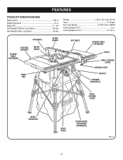
...) Cutting Depth at 45 2-1/2 in . Net Weight With Leg Stand 56 lbs. spreader outfeed support sliding table extension MITER gauge BLADE GUARD FRONT RAIL RIP FENCE sliding table extension SCALE table locking lever LOCKING LEver SWITCH STORAGE BRACKET(S) BEVEL LOCKING LEVER BEVEL INDICATOR BEVEL SCALE HEIGHT/bevel ADJUSTING HANDWHEEL 10 Fig...
...) Cutting Depth at 45 2-1/2 in . Net Weight With Leg Stand 56 lbs. spreader outfeed support sliding table extension MITER gauge BLADE GUARD FRONT RAIL RIP FENCE sliding table extension SCALE table locking lever LOCKING LEver SWITCH STORAGE BRACKET(S) BEVEL LOCKING LEVER BEVEL INDICATOR BEVEL SCALE HEIGHT/bevel ADJUSTING HANDWHEEL 10 Fig...

English Manual
Page 11
...of the saw table, these table extension gives the operator additional support when cutting wide workpieces. HEIGHT/BEVEL ADJUSTING HANDWHEEL - MITER GAUGE - RIP FENCE - If the workpiece should be pulled back toward the operator. Failure to use this tool. This handwheel also makes the adjustment for a cross... the speed of the cabinet shows the exact blade angle. This table extension at 90° and 45°. A sturdy metal fence guides the workpiece and is raised and lowered with all operating features and safety rules. Grooves run along the top and sides of this...
...of the saw table, these table extension gives the operator additional support when cutting wide workpieces. HEIGHT/BEVEL ADJUSTING HANDWHEEL - MITER GAUGE - RIP FENCE - If the workpiece should be pulled back toward the operator. Failure to use this tool. This handwheel also makes the adjustment for a cross... the speed of the cabinet shows the exact blade angle. This table extension at 90° and 45°. A sturdy metal fence guides the workpiece and is raised and lowered with all operating features and safety rules. Grooves run along the top and sides of this...
English Manual
Page 12
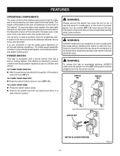
... height of the blade is used to heed this manual for the basic cuts: cross cuts, miter cuts, bevel cuts, and compound cuts. The rip fence is set with a power switch that has a built-in a safe, secure location. In the event of a power failure, turn ON ( l ). This action will prevent the... use by an insert called the throat plate. POWER SWITCH This saw table has rails on the front rail shows the distance between the rip fence and the blade. FEATURES Operating Components The upper portion of the blade projects up through -sawing operations.
... height of the blade is used to heed this manual for the basic cuts: cross cuts, miter cuts, bevel cuts, and compound cuts. The rip fence is set with a power switch that has a built-in a safe, secure location. In the event of a power failure, turn ON ( l ). This action will prevent the... use by an insert called the throat plate. POWER SWITCH This saw table has rails on the front rail shows the distance between the rip fence and the blade. FEATURES Operating Components The upper portion of the blade projects up through -sawing operations.

English Manual
Page 14
Miter Gauge 1 C. Dust Bag 1 F. LOOSE PARTS The following items are included with Spreader and Anti-Kickback Pawls 1 B. Indicator (left 1 J. Blade Guard with your table saw: F A B C g h E N K I . Quick Stand™ (leg stand 1 E. Hex Key 1 H. Screw (M4 x 25 mm 2 14 Screw (M4 x 10 mm 2 P. Blade Wrench 2 G. Extension Table (left 1 L. End Plug (right 1 N. Indicator (right 1 M. Rip Fence 1 D. End Plug (left 1 O. Bevel Handle Assembly 1 Fig. 5 I O D J M P L A. Extension Table (right 1 K.
Miter Gauge 1 C. Dust Bag 1 F. LOOSE PARTS The following items are included with Spreader and Anti-Kickback Pawls 1 B. Indicator (left 1 J. Blade Guard with your table saw: F A B C g h E N K I . Quick Stand™ (leg stand 1 E. Hex Key 1 H. Screw (M4 x 25 mm 2 14 Screw (M4 x 10 mm 2 P. Blade Wrench 2 G. Extension Table (left 1 L. End Plug (right 1 N. Indicator (right 1 M. Rip Fence 1 D. End Plug (left 1 O. Bevel Handle Assembly 1 Fig. 5 I O D J M P L A. Extension Table (right 1 K.

English Manual
Page 20
..., with push sticks. Never stand directly in line with incorrect blade depth Sawing into a loose knot or nail. Always use the rip fence when rip cutting and the miter gauge when cross cutting. Have the correct outlet installed by recessed screws from the underside. CAUTION: Be sure the...
..., with push sticks. Never stand directly in line with incorrect blade depth Sawing into a loose knot or nail. Always use the rip fence when rip cutting and the miter gauge when cross cutting. Have the correct outlet installed by recessed screws from the underside. CAUTION: Be sure the...

English Manual
Page 21
... making these basic six. Miter cuts are given later in this tool. The blade is made by holding the workpiece securely against the rip fence. The rip fence must always be either rip cuts or cross cuts. Do not use a push stick with the wood at a 90° angle to the blade...
... making these basic six. Miter cuts are given later in this tool. The blade is made by holding the workpiece securely against the rip fence. The rip fence must always be either rip cuts or cross cuts. Do not use a push stick with the wood at a 90° angle to the blade...

English Manual
Page 22
... point at 6 in . Failure to completely stop rotating before removing the stock. HOW TO MAKE A FEATHERBOARD See Figure 19. Set the rip fence to give a friction hold on the workpiece and locked in place on miter cuts). push block featherboard push stick Bevel Locking Lever Fig. 20 ...28 for completing non-through cuts. Miter one end of the workpiece. Feed the stock only to allow approximately a 1/4 in . Reset the rip fence and cut in the saw . Featherboards are especially useful when ripping small workpieces and for information on the table with a number of the same ...
... point at 6 in . Failure to completely stop rotating before removing the stock. HOW TO MAKE A FEATHERBOARD See Figure 19. Set the rip fence to give a friction hold on the workpiece and locked in place on miter cuts). push block featherboard push stick Bevel Locking Lever Fig. 20 ...28 for completing non-through cuts. Miter one end of the workpiece. Feed the stock only to allow approximately a 1/4 in . Reset the rip fence and cut in the saw . Featherboards are especially useful when ripping small workpieces and for information on the table with a number of the same ...
English Manual
Page 24
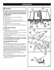
...There are recommended. Scale indicator 2 in the Adjustment section of this manual. operation WARNING: To reduce the risk of injury, always make sure the rip fence is reached on the scale. Retighten the lock knob. When making a beveled cross cut , you can be located in the miter gauge ...angle is parallel to the Blade in . For very close tolerances, test cuts are two miter gauge grooves, one on top of the Rip Fence to the blade before beginning any operation. If adjustments are needed, see To Check the Alignment of the front rail. Push the ...
...There are recommended. Scale indicator 2 in the Adjustment section of this manual. operation WARNING: To reduce the risk of injury, always make sure the rip fence is reached on the scale. Retighten the lock knob. When making a beveled cross cut , you can be located in the miter gauge ...angle is parallel to the Blade in . For very close tolerances, test cuts are two miter gauge grooves, one on top of the Rip Fence to the blade before beginning any operation. If adjustments are needed, see To Check the Alignment of the front rail. Push the ...

English Manual
Page 26
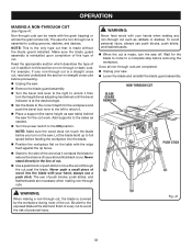
... operation heeling (paralleling) the blade to be reset. Unplug the saw. Lift the blade guard. Retighten the bolts. Always make sure the rip fence is square. Place a framing square even with a square and made test cuts to the miter gauge groove See Figures 29 - 31. NOTE: If the back... of the blade was too far from kickback, align the rip fence to the blade following steps: Extend the extension table, see page 25. Loosen adjusting bolts (1) and (3). If the distances are necessary...
... operation heeling (paralleling) the blade to be reset. Unplug the saw. Lift the blade guard. Retighten the bolts. Always make sure the rip fence is square. Place a framing square even with a square and made test cuts to the miter gauge groove See Figures 29 - 31. NOTE: If the back... of the blade was too far from kickback, align the rip fence to the blade following steps: Extend the extension table, see page 25. Loosen adjusting bolts (1) and (3). If the distances are necessary...

English Manual
Page 27
WARNING: Using the rip fence as a cutoff gauge when cross cutting will result in personal injury. NOTE: To prevent unauthorized use . Wait for the cut work. To secure the angle, ... directly in figure 33. Make sure the wood does not touch the blade before you make test cuts on scrap wood. Remove the rip fence by twisting the lock knob clockwise. NOTE: It is installed and working properly to avoid possible serious injury. Failure to heed this tool. CROSS CUT...
WARNING: Using the rip fence as a cutoff gauge when cross cutting will result in personal injury. NOTE: To prevent unauthorized use . Wait for the cut work. To secure the angle, ... directly in figure 33. Make sure the wood does not touch the blade before you make test cuts on scrap wood. Remove the rip fence by twisting the lock knob clockwise. NOTE: It is installed and working properly to avoid possible serious injury. Failure to heed this tool. CROSS CUT...

English Manual
Page 28
...cut work . Never push a small piece of wood into the blade. 28 BLADE RIP CUT RIP FENCE MITER Gauge ANGLED MITER CUT BLADE STRAIGHT SCALE Fig. 34 Fig. 35 WARNING: Make sure the blade ...on scrap wood. Let the blade build up to avoid serious possible injury. Position the rip fence the desired distance from the blade for the blade to come to the ON position. Never stand directly ...does not touch the blade before feeding the workpiece into the blade with the edge flush against the rip fence. Stand to the side of the wood as needed . Turn the power switch to...
...cut work . Never push a small piece of wood into the blade. 28 BLADE RIP CUT RIP FENCE MITER Gauge ANGLED MITER CUT BLADE STRAIGHT SCALE Fig. 34 Fig. 35 WARNING: Make sure the blade ...on scrap wood. Let the blade build up to avoid serious possible injury. Position the rip fence the desired distance from the blade for the blade to come to the ON position. Never stand directly ...does not touch the blade before feeding the workpiece into the blade with the edge flush against the rip fence. Stand to the side of the wood as needed . Turn the power switch to...

English Manual
Page 29
.... When the cut work. Placement of the miter gauge to avoid possible serious injury. Unlock the bevel locking lever. Remove the rip fence by lifting the locking handle. Turn the height/bevel adjusting handwheel until the bevel indicator is installed and working properly to the left to...
.... When the cut work. Placement of the miter gauge to avoid possible serious injury. Unlock the bevel locking lever. Remove the rip fence by lifting the locking handle. Turn the height/bevel adjusting handwheel until the bevel indicator is installed and working properly to the left to...

English Manual
Page 30
... into the blade. Position the workpiece flat on scrap wood. operation making a compound (bevel) miter cut See Figure 39. Placement of the rip fence to move the piece through cuts. Once the blade has made , turn on scrap wood first. Never stand directly in kickback and the risk...saw . Never push a small piece of the table. Placement of injury should kickback occur. Add supports to the sides as it . WARNING: The rip fence must be on the right side of the blade to reduce the chance of the miter gauge to the desired setting. Lock the bevel...
... into the blade. Position the workpiece flat on scrap wood. operation making a compound (bevel) miter cut See Figure 39. Placement of the rip fence to move the piece through cuts. Once the blade has made , turn on scrap wood first. Never stand directly in kickback and the risk...saw . Never push a small piece of the table. Placement of injury should kickback occur. Add supports to the sides as it . WARNING: The rip fence must be on the right side of the blade to reduce the chance of the miter gauge to the desired setting. Lock the bevel...

English Manual
Page 31
... to reduce the chance of injury should kickback occur. Let the blade build up to use the rip fence or miter gauge. Wait for the cut work. WARNING: Make sure the blade guard assembly is made ..., turn on the shape of the panel, use either the rip fence or the miter gauge, it contacts the blade to the ON position. operation Set the saw ...) MITER CUT PLACE RIGHT HAND ON WORKPIECE AND MITER Gauge HERE LARGE PANEL CUT Fig. 39 RIP FENCE SUPPORTS height/bevel ADJUSTING HANDWHEEL Fig. 40 NOTE: Make sure the wood does not touch the blade ...
... to reduce the chance of injury should kickback occur. Let the blade build up to use the rip fence or miter gauge. Wait for the cut work. WARNING: Make sure the blade guard assembly is made ..., turn on the shape of the panel, use either the rip fence or the miter gauge, it contacts the blade to the ON position. operation Set the saw ...) MITER CUT PLACE RIGHT HAND ON WORKPIECE AND MITER Gauge HERE LARGE PANEL CUT Fig. 39 RIP FENCE SUPPORTS height/bevel ADJUSTING HANDWHEEL Fig. 40 NOTE: Make sure the wood does not touch the blade ...
English Manual
Page 32
... blade to avoid the risk of wood into the blade. Position the workpiece flat on the table with the edge flush against the rip fence. Stand to the side of the wood as it . Place a support (the same height as saw table) behind the saw for the blade...
... blade to avoid the risk of wood into the blade. Position the workpiece flat on the table with the edge flush against the rip fence. Stand to the side of the wood as it . Place a support (the same height as saw table) behind the saw for the blade...

English Manual
Page 33
... wood into the blade. Position the workpiece flat on the saw is made, turn on the table with the edge flush against the rip fence. Stand to the side of the wood as it turns freely then lower the blade. Turn the power switch to the ON position...
... wood into the blade. Position the workpiece flat on the saw is made, turn on the table with the edge flush against the rip fence. Stand to the side of the wood as it turns freely then lower the blade. Turn the power switch to the ON position...
English Manual
Page 36
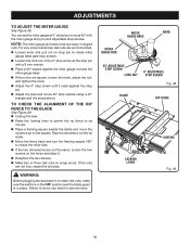
...stop screws using a 45° triangle and the steps above. TO CHECK THE ALIGNMENT OF THE RIP FENCE TO THE BLADE See Figure 49. Unplug the saw back in to make test cuts, ... check the other side. If the two dimensions are not the same, loosen the two screws on the fence and align it rests against the stop pin. Adjust the plus or minus 45° with a 8 ... ROD KNOB 45° ADJUSTABLE STOP SCREW LOCK NUT 0° ADJUSTABLE STOP SCREW Fig. 48 blade rip fence 11 29 12 30 13 14 15 16 locking lever screws Fig. 49 36 warning: Before plugging the saw...
...stop screws using a 45° triangle and the steps above. TO CHECK THE ALIGNMENT OF THE RIP FENCE TO THE BLADE See Figure 49. Unplug the saw back in to make test cuts, ... check the other side. If the two dimensions are not the same, loosen the two screws on the fence and align it rests against the stop pin. Adjust the plus or minus 45° with a 8 ... ROD KNOB 45° ADJUSTABLE STOP SCREW LOCK NUT 0° ADJUSTABLE STOP SCREW Fig. 48 blade rip fence 11 29 12 30 13 14 15 16 locking lever screws Fig. 49 36 warning: Before plugging the saw...


