Operation Manual
Page 5
... : a) Keeping blade sharp. SPECIFIC SAFETY RULES workpiece through the blade instead of using your hand to the rear and sides of the saw table for wide or long workpieces. AVOID KICKBACKS (work thrown back toward you loan someone this manual or addendums. Use of kickback.... BEFORE performing any operation freehand. e) Pay particular attention to instruct other users. d) Not releasing the work using the table saw blade using a push stick. b) Use saw blade guard and riving knife for every operation for safe use to instructions on floor or below waist height. ...
... : a) Keeping blade sharp. SPECIFIC SAFETY RULES workpiece through the blade instead of using your hand to the rear and sides of the saw table for wide or long workpieces. AVOID KICKBACKS (work thrown back toward you loan someone this manual or addendums. Use of kickback.... BEFORE performing any operation freehand. e) Pay particular attention to instruct other users. d) Not releasing the work using the table saw blade using a push stick. b) Use saw blade guard and riving knife for every operation for safe use to instructions on floor or below waist height. ...
Operation Manual
Page 8
...material from a block so the end (or part of the spinning blade. Compound Cut A cross cut . Dado Cut (table saws and compound sliding miter saws) A non-through cut without the workpiece being done. Snipe (planers) Depression made across the grain or the width of ... Surface where the workpiece rests while performing a cutting, drilling, planing, or sanding operation. 8 - Non-Through Cuts (table saws and compound sliding miter saws) Any cutting operation where the blade does not extend completely through the thickness of cut will not cut or the slot ...
...material from a block so the end (or part of the spinning blade. Compound Cut A cross cut . Dado Cut (table saws and compound sliding miter saws) A non-through cut without the workpiece being done. Snipe (planers) Depression made across the grain or the width of ... Surface where the workpiece rests while performing a cutting, drilling, planing, or sanding operation. 8 - Non-Through Cuts (table saws and compound sliding miter saws) Any cutting operation where the blade does not extend completely through the thickness of cut will not cut or the slot ...

Operation Manual
Page 10
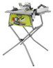
.... MITER GAUGE GROOVES - Push stick storage is recommended that you with the height/bevel adjusting handwheel. This saw table. BEVEL SCALE - Bevel angles are locked with the saw table. BEVEL LOCKING LEVER - Convenient storage for specific operations such as a knowledge of the project you are available... for a cross cut . English This handwheel also makes the adjustment for rip cuts. RIP FENCE - FEATURES KNOW YOUR TABLE SAW See Figure 2. BLADE GUARD - Always keep the kerf open and prevent kickback. Located on the front of kickback.
.... MITER GAUGE GROOVES - Push stick storage is recommended that you with the height/bevel adjusting handwheel. This saw table. BEVEL SCALE - Bevel angles are locked with the saw table. BEVEL LOCKING LEVER - Convenient storage for specific operations such as a knowledge of the project you are available... for a cross cut . English This handwheel also makes the adjustment for rip cuts. RIP FENCE - FEATURES KNOW YOUR TABLE SAW See Figure 2. BLADE GUARD - Always keep the kerf open and prevent kickback. Located on the front of kickback.

Operation Manual
Page 13
Rip Fence 1 F. English Handle Assembly 1 D. Hex Key (5 mm 1 G. Support bracket (outside 1 J. Closed End Wrench 1 R. Handle End Cap 1 E. Leg Stand Bolts 2 O. LOOSE PARTS The following items are included with anti-kickback pawls 1 B. Stand hinge (F 1 H. Stand legs 4 L. Open End Wrench 1 13 - Wing Nuts 4 M. Miter Gauge 1 C. Push Stick 1 Q. Hex Nuts 2 P. Stand hinge (R 1 I N O N O K K P Q R Fig. 5 A. Carriage Bolts 4 N. Blade Guard with your table saw: A F M L B E C G H L M J D I . Support bracket (inside 1 K.
Rip Fence 1 F. English Handle Assembly 1 D. Hex Key (5 mm 1 G. Support bracket (outside 1 J. Closed End Wrench 1 R. Handle End Cap 1 E. Leg Stand Bolts 2 O. LOOSE PARTS The following items are included with anti-kickback pawls 1 B. Stand hinge (F 1 H. Stand legs 4 L. Open End Wrench 1 13 - Wing Nuts 4 M. Miter Gauge 1 C. Push Stick 1 Q. Hex Nuts 2 P. Stand hinge (R 1 I N O N O K K P Q R Fig. 5 A. Carriage Bolts 4 N. Blade Guard with your table saw: A F M L B E C G H L M J D I . Support bracket (inside 1 K.

Operation Manual
Page 14
...leg stand. WARNING: To avoid serious personal injury, always make sure the table saw on the floor. NEVER operate the saw is complete. To mount the saw must be mounted to a firm supporting surface such as a workbench or leg...Do not connect to the blade. Tighten all loose parts, and satisfactorily operated the tool. The saw is misuse and could result in serious personal injury. Any such alteration or modification is factory set for accuracy.... this tool until you unpack it. MOUNTING HOLES The table saw to the leg stand, refer to a work surface. To mount the...
...leg stand. WARNING: To avoid serious personal injury, always make sure the table saw on the floor. NEVER operate the saw is complete. To mount the saw must be mounted to a firm supporting surface such as a workbench or leg...Do not connect to the blade. Tighten all loose parts, and satisfactorily operated the tool. The saw is misuse and could result in serious personal injury. Any such alteration or modification is factory set for accuracy.... this tool until you unpack it. MOUNTING HOLES The table saw to the leg stand, refer to a work surface. To mount the...

Operation Manual
Page 15
... 9. NOTE: Do not use . Install hardware through the holes in the brackets and frame. Hold it close to its fully extended position. Position the table saw onto the stand so that all the stand legs are aligned with wing nuts and tighten securely. Be sure the... table saw 's frame is sturdy before use this leg stand with other equipment or for other purposes. Lay outside support bracket with the top rails facing ...
... 9. NOTE: Do not use . Install hardware through the holes in the brackets and frame. Hold it close to its fully extended position. Position the table saw onto the stand so that all the stand legs are aligned with wing nuts and tighten securely. Be sure the... table saw 's frame is sturdy before use this leg stand with other equipment or for other purposes. Lay outside support bracket with the top rails facing ...

Operation Manual
Page 21
ASSEMBLY STORING TABLE SAW ACCESSORIES See Figures 17 and 18. When not in use the storage area, insert the tip of the saw table, secured by a wing nut. To use , wrenches and the push stick may be stored on top of the rip fence. English PUSH STICK STORAGE RIP FENCE Fig. 17 BLADE WRENCH STORAGE BLADE WRENCHES PUSH STICK WING NUT Fig. 18 21 - Additional storage for the push stick is located on the underside of the push stick into the slot until it clicks into place.
ASSEMBLY STORING TABLE SAW ACCESSORIES See Figures 17 and 18. When not in use the storage area, insert the tip of the saw table, secured by a wing nut. To use , wrenches and the push stick may be stored on top of the rip fence. English PUSH STICK STORAGE RIP FENCE Fig. 17 BLADE WRENCH STORAGE BLADE WRENCHES PUSH STICK WING NUT Fig. 18 21 - Additional storage for the push stick is located on the underside of the push stick into the slot until it clicks into place.
Operation Manual
Page 22
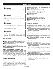
...cross cutting, ripping, mitering, beveling, and compound cutting Dado with optional accessories Cabinet making and woodworking NOTE: This table saw is designed to cut . APPLICATIONS You may contact the blade. Do not modify the plug if it occur. CAUSES OF KICKBACK Kickback .... Always use clean, sharp, and properly-set blade WARNING: AVOIDING KICKBACK Do not use steady, even pressure. BASIC OPERATION OF THE TABLE SAW The 3-prong plug must be plugged into knots or nails in the workpiece Twisting the wood while making a cut Failing to...
...cross cutting, ripping, mitering, beveling, and compound cutting Dado with optional accessories Cabinet making and woodworking NOTE: This table saw is designed to cut . APPLICATIONS You may contact the blade. Do not modify the plug if it occur. CAUSES OF KICKBACK Kickback .... Always use clean, sharp, and properly-set blade WARNING: AVOIDING KICKBACK Do not use steady, even pressure. BASIC OPERATION OF THE TABLE SAW The 3-prong plug must be plugged into knots or nails in the workpiece Twisting the wood while making a cut Failing to...

Operation Manual
Page 26
This table saw has a rack and pinion bevel control that the outer points of the blade are below the top surface.... it back to the left . TO ADJUST THE BEVEL INDICATOR See Figure 27. If the bevel indicator is not at zero when the saw . Loosen bevel control by approximately 1/8 in . TO CHANGE BLADE ANGLE (BEVEL) See Figure 26. Rotate to 45°....: A 90° cut has a 0° bevel and a 45° cut has a 45° bevel. Unplug the saw blade is securely tightened. If it needs to be set so that allows you to make angled cuts from 90° to the right again...
This table saw has a rack and pinion bevel control that the outer points of the blade are below the top surface.... it back to the left . TO ADJUST THE BEVEL INDICATOR See Figure 27. If the bevel indicator is not at zero when the saw . Loosen bevel control by approximately 1/8 in . TO CHANGE BLADE ANGLE (BEVEL) See Figure 26. Rotate to 45°....: A 90° cut has a 0° bevel and a 45° cut has a 45° bevel. Unplug the saw blade is securely tightened. If it needs to be set so that allows you to make angled cuts from 90° to the right again...

Operation Manual
Page 29
...hazard which could result in personal injury. English NOTE: It is recommended that you place the piece to handle and properly support the table saw stand is on the left side of room to be used. Check again for squareness and continue to make sure that does not ...provide adequate space and stable footing for the table saw is parallel to the blade before connecting saw . Turn adjusting bolt left . Operating the saw in a location that the table saw and the workpiece. DO NOT attempt to adjust if needed. WARNING: Do not ...
...hazard which could result in personal injury. English NOTE: It is recommended that you place the piece to handle and properly support the table saw stand is on the left side of room to be used. Check again for squareness and continue to make sure that does not ...provide adequate space and stable footing for the table saw is parallel to the blade before connecting saw . Turn adjusting bolt left . Operating the saw in a location that the table saw and the workpiece. DO NOT attempt to adjust if needed. WARNING: Do not ...

Operation Manual
Page 32
MITER CUT BLADE STRAIGHT MITER GAUGE ANGLED Fig. 37 VIEWED FROM THE FRONT, BELOW THE TABLE SAW BEVEL LOCKING LEVER TO TIGHTEN WARNING: The miter gauge must be on the right side of the blade before moving the workpiece into the blade. &#... knob. Make sure the wood is installed and working properly to full speed before turning on the saw. Turn the saw on the workpiece. When the cut is made, turn the saw off. OPERATION MAKING A MITER CUT See Figure 37. English TO LOOSEN HEIGHT/BEVEL ADJUSTING HANDWHEEL Fig. 38 NOTE...
MITER CUT BLADE STRAIGHT MITER GAUGE ANGLED Fig. 37 VIEWED FROM THE FRONT, BELOW THE TABLE SAW BEVEL LOCKING LEVER TO TIGHTEN WARNING: The miter gauge must be on the right side of the blade before moving the workpiece into the blade. &#... knob. Make sure the wood is installed and working properly to full speed before turning on the saw. Turn the saw on the workpiece. When the cut is made, turn the saw off. OPERATION MAKING A MITER CUT See Figure 37. English TO LOOSEN HEIGHT/BEVEL ADJUSTING HANDWHEEL Fig. 38 NOTE...

Operation Manual
Page 37
... this procedure (see the Accessories section of the cut to full speed before feeding the workpiece into the blade with the retailer where the table saw off. NOTE: Always store the blade washer and throat plate in locked position. Install the dado throat plate and rotate the blade by the ... REMOVED DADO CUT Fig. 44 37 - Do not use with the edge flush against the rip fence or miter gauge and hold firmly against the saw table. Use a push block or push stick to move the wood through cuts. When the cut past a securely tightened blade nut. Place ...
... this procedure (see the Accessories section of the cut to full speed before feeding the workpiece into the blade with the retailer where the table saw off. NOTE: Always store the blade washer and throat plate in locked position. Install the dado throat plate and rotate the blade by the ... REMOVED DADO CUT Fig. 44 37 - Do not use with the edge flush against the rip fence or miter gauge and hold firmly against the saw table. Use a push block or push stick to move the wood through cuts. When the cut past a securely tightened blade nut. Place ...
Parts Diagram
Page 1
RYOBI 10 in. P.O. Box 1288, Anderson, SC 29622 • Phone 1-800-525-2579 www.ryobitools.com TABLE SAW MODEL NUMBER RTS11 REPAIR SHEET ONE WORLD TECHNOLOGIES, INC.
RYOBI 10 in. P.O. Box 1288, Anderson, SC 29622 • Phone 1-800-525-2579 www.ryobitools.com TABLE SAW MODEL NUMBER RTS11 REPAIR SHEET ONE WORLD TECHNOLOGIES, INC.
Parts Diagram
Page 3
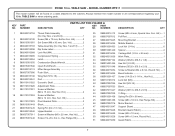
PARTS LIST FOR FIGURE A KEY PART KEY PART NO. NUMBER DESCRIPTION QTY NO. RYOBI 10 in ., Hex Hd 2 39 089110101012 Lock Nut (M5 1 40 089037007034 Hex Nut (3/8-16 2 41 089037007033 Block 1 42 089037011047...Spacer 2 31 089240015034 Carriage Bolt (1/4 in. Soc. MODEL NUMBER RTS11 The model number will be found on a label attached to the cabinet. Hd 2 4 089240015703 Table Assembly (Inc. Hd 2 3 089015001001 Set Screw (M8 x 30 mm, Soc. TABLE SAW - TABLE SAW or when ordering parts. Hd 2 18 089110101024 Screw w/Washer (M6...
PARTS LIST FOR FIGURE A KEY PART KEY PART NO. NUMBER DESCRIPTION QTY NO. RYOBI 10 in ., Hex Hd 2 39 089110101012 Lock Nut (M5 1 40 089037007034 Hex Nut (3/8-16 2 41 089037007033 Block 1 42 089037011047...Spacer 2 31 089240015034 Carriage Bolt (1/4 in. Soc. MODEL NUMBER RTS11 The model number will be found on a label attached to the cabinet. Hd 2 4 089240015703 Table Assembly (Inc. Hd 2 3 089015001001 Set Screw (M8 x 30 mm, Soc. TABLE SAW - TABLE SAW or when ordering parts. Hd 2 18 089110101024 Screw w/Washer (M6...
Parts Diagram
Page 4
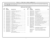
.... 2 and 6-8) 089240015906 Styrofoam Removal Warning Label 995000347 Operator's Manual (089240015802) 8-31-18 (Rev:04) 4 TABLE SAW or when ordering parts. Always mention the model number in all correspondence regarding your 10 in ., 24 Tooth 1 69...Hex Soc. PARTS LIST FOR FIGURE A KEY PART NO. Hd 1 68 089240015207 Blade (10 in . MODEL NUMBER RTS11 The model number will be found on a label attached to the cabinet. Key Nos. 80-85 1 80 089037007912...1 Not Shown: 089240015199 Optional Dado Throat Plate Assembly (Inc. RYOBI 10 in.
.... 2 and 6-8) 089240015906 Styrofoam Removal Warning Label 995000347 Operator's Manual (089240015802) 8-31-18 (Rev:04) 4 TABLE SAW or when ordering parts. Always mention the model number in all correspondence regarding your 10 in ., 24 Tooth 1 69...Hex Soc. PARTS LIST FOR FIGURE A KEY PART NO. Hd 1 68 089240015207 Blade (10 in . MODEL NUMBER RTS11 The model number will be found on a label attached to the cabinet. Key Nos. 80-85 1 80 089037007912...1 Not Shown: 089240015199 Optional Dado Throat Plate Assembly (Inc. RYOBI 10 in.
Parts Diagram
Page 6
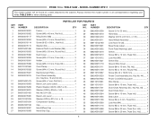
... Lock Nut (M4 1 53 089240015116 Screw (M4 x 10 mm, Truss Hd 2 54 089240015088 Screw (M6 x 30 mm, Truss Soc. TABLE SAW or when ordering parts. NUMBER DESCRIPTION QTY 1 089240015001 2 089240015002 3 089240015117 4 089240015004 5 089240015114 6 089240015115 7 080015001496 8 089240015003 9 089240015092 10...28 089240015009 Screw (1/4 x 55 mm 1 29 089240015010 Hand Grip 1 30 080015001479 Washer (OD13 x ID1/4 in . RYOBI 10 in . MODEL NUMBER RTS11 The model number will be found on a label attached to the cabinet. Key No. 44)...... 1 44 089037007902 Power ...
... Lock Nut (M4 1 53 089240015116 Screw (M4 x 10 mm, Truss Hd 2 54 089240015088 Screw (M6 x 30 mm, Truss Soc. TABLE SAW or when ordering parts. NUMBER DESCRIPTION QTY 1 089240015001 2 089240015002 3 089240015117 4 089240015004 5 089240015114 6 089240015115 7 080015001496 8 089240015003 9 089240015092 10...28 089240015009 Screw (1/4 x 55 mm 1 29 089240015010 Hand Grip 1 30 080015001479 Washer (OD13 x ID1/4 in . RYOBI 10 in . MODEL NUMBER RTS11 The model number will be found on a label attached to the cabinet. Key No. 44)...... 1 44 089037007902 Power ...

Parts Diagram
Page 8
... 089240015167 Fence Bracket 1 18 089240015169 Glide Block 2 19 089240015170 Screw (8-32 x 8.5 mm, Flat Hd 2 20 089240015168 Indicator 1 21 089240015197 Screw (M4 x 10 mm, Truss Hd 1 8 TABLE SAW - RYOBI 10 in . TABLE SAW or when ordering parts. MODEL NUMBER RTS11 The model number will be found on a label attached to the cabinet.
... 089240015167 Fence Bracket 1 18 089240015169 Glide Block 2 19 089240015170 Screw (8-32 x 8.5 mm, Flat Hd 2 20 089240015168 Indicator 1 21 089240015197 Screw (M4 x 10 mm, Truss Hd 1 8 TABLE SAW - RYOBI 10 in . TABLE SAW or when ordering parts. MODEL NUMBER RTS11 The model number will be found on a label attached to the cabinet.

Parts Diagram
Page 9
Always mention the model number in all correspondence regarding your 10 in ., Round. TABLE SAW or when ordering parts. FIGURE D 9 8 7 6 5 PARTS LIST FOR FIGURE D KEY PART NO. NUMBER DESCRIPTION QTY 1 089240015177 Miter Gauge Rod 1 2 080015001563 Pointer... 1 6 080015001475 Nylon Washer (OD16 x ID6.5 x 2t 1 7 080015001560 Washer (OD16 x ID6.5 x 2t 1 8 089040002005 Miter Gauge Knob 1 9 089040002006 Miter Gauge Cap 1 1 4 3 2 9 TABLE SAW - MODEL NUMBER RTS11 The model number will be found on a label attached to the cabinet. RYOBI 10 in.
Always mention the model number in all correspondence regarding your 10 in ., Round. TABLE SAW or when ordering parts. FIGURE D 9 8 7 6 5 PARTS LIST FOR FIGURE D KEY PART NO. NUMBER DESCRIPTION QTY 1 089240015177 Miter Gauge Rod 1 2 080015001563 Pointer... 1 6 080015001475 Nylon Washer (OD16 x ID6.5 x 2t 1 7 080015001560 Washer (OD16 x ID6.5 x 2t 1 8 089040002005 Miter Gauge Knob 1 9 089040002006 Miter Gauge Cap 1 1 4 3 2 9 TABLE SAW - MODEL NUMBER RTS11 The model number will be found on a label attached to the cabinet. RYOBI 10 in.

Parts Diagram
Page 10
MODEL NUMBER RTS11 20 21 19 18 7 8 11 3 14 13 12 10 9 87 6 1 1 2 4 15 17 17 16 14 5 NOTE: The assembly shown represents an important part of alteration or damage to the system, service should be performed by your nearest Ryobi Authorized Service Center for service. 10 Contact your nearest Ryobi Authorized Service Center. To avoid the possibility of the double insulated system. FIGURE E RYOBI 10 in. TABLE SAW -
MODEL NUMBER RTS11 20 21 19 18 7 8 11 3 14 13 12 10 9 87 6 1 1 2 4 15 17 17 16 14 5 NOTE: The assembly shown represents an important part of alteration or damage to the system, service should be performed by your nearest Ryobi Authorized Service Center for service. 10 Contact your nearest Ryobi Authorized Service Center. To avoid the possibility of the double insulated system. FIGURE E RYOBI 10 in. TABLE SAW -

Parts Diagram
Page 11
MODEL NUMBER RTS11 The model number will be found on a label attached to the cabinet. Always ...1 20 089240015139 Gear Box Cover 1 21 089110101012 Lock Nut (M5 1 11 NUMBER DESCRIPTION QTY 1 089240015141 Screw w/Washer (M5 x 60 mm, Round. TABLE SAW or when ordering parts. Hd 2 2 089110101081 Wire Clamp 1 3 089037011050 Screw w/Washer (M5 x 35 mm, Round. PARTS LIST FOR FIGURE E KEY...Washer (M5 x 65 mm, Truss Hd.)...... 2 15 089037011708 Armature Assembly w/Bearings 1 16 089110101220 Screw (8-32 x 3/8 in . RYOBI 10 in. TABLE SAW -
MODEL NUMBER RTS11 The model number will be found on a label attached to the cabinet. Always ...1 20 089240015139 Gear Box Cover 1 21 089110101012 Lock Nut (M5 1 11 NUMBER DESCRIPTION QTY 1 089240015141 Screw w/Washer (M5 x 60 mm, Round. TABLE SAW or when ordering parts. Hd 2 2 089110101081 Wire Clamp 1 3 089037011050 Screw w/Washer (M5 x 35 mm, Round. PARTS LIST FOR FIGURE E KEY...Washer (M5 x 65 mm, Truss Hd.)...... 2 15 089037011708 Armature Assembly w/Bearings 1 16 089110101220 Screw (8-32 x 3/8 in . RYOBI 10 in. TABLE SAW -


