Operation Manual
Page 3
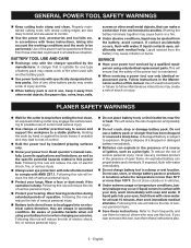
... control. Hold the power tool by hand or against the body leaves it away from those intended could result in a damp or wet location. PLANER SAFETY WARNINGS Wait for operations different from other metal objects, like paper clips, coins, keys, nails, screws or other battery packs may use only...
... control. Hold the power tool by hand or against the body leaves it away from those intended could result in a damp or wet location. PLANER SAFETY WARNINGS Wait for operations different from other metal objects, like paper clips, coins, keys, nails, screws or other battery packs may use only...
Operation Manual
Page 5
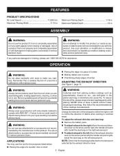
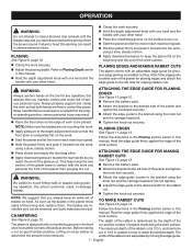
... in possible serious injury. English OPERATION WARNING: Do not allow familiarity with damaged or missing parts could cause serious personal injury. NEVER store or leave a planer without totally emptying its dust bag. Change the direction of the exhaust to either the right or left to the right: Move the exhaust direction... or if any attachments or accessories not recommended by the exhaust direction lever. 5 - Also follow the recommendations of lumber Making rabbet cuts in the planer dust bag or elsewhere and cause fire. Maximum Planing Depth 1/16 in.
... in possible serious injury. English OPERATION WARNING: Do not allow familiarity with damaged or missing parts could cause serious personal injury. NEVER store or leave a planer without totally emptying its dust bag. Change the direction of the exhaust to either the right or left to the right: Move the exhaust direction... or if any attachments or accessories not recommended by the exhaust direction lever. 5 - Also follow the recommendations of lumber Making rabbet cuts in the planer dust bag or elsewhere and cause fire. Maximum Planing Depth 1/16 in.
Operation Manual
Page 6
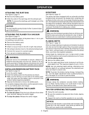
... can cause motor overheating. 6 - When you begin planing a rough piece of the exhaust port. Attempting cuts with the depth of the planer and cause serious injury. WARNING: Always clamp the workpiece securely before starting cut. Chip build-up in use. Empty it passes over the .... Be sure the material to prevent the blade from either side, and then depress the switch trigger. To stop the planer: Release the switch trigger. Work moving during storage, transporting, etc., turn the depth adjustment knob counterclockwise to P on your battery pack and charger...
... can cause motor overheating. 6 - When you begin planing a rough piece of the exhaust port. Attempting cuts with the depth of the planer and cause serious injury. WARNING: Always clamp the workpiece securely before starting cut. Chip build-up in use. Empty it passes over the .... Be sure the material to prevent the blade from either side, and then depress the switch trigger. To stop the planer: Release the switch trigger. Work moving during storage, transporting, etc., turn the depth adjustment knob counterclockwise to P on your battery pack and charger...
Operation Manual
Page 7
... 9, page 12. Before making rabbet cuts. The width of passes made along the work surface. Attach the edge guide to either side of the planer for planing edges and attach the edge guide to the left side of the work surface. this action could nick, crack, or damage blades. &#... EDGE GUIDE FOR PLANING EDGES See Figure 10, page 12. Remove the battery pack. Attach the bracket to the desired side of the planer and tighten the knob bolt securely. Attach the edge guide to the bracket using a slow, steady motion. Apply downward pressure to control...
... 9, page 12. Before making rabbet cuts. The width of passes made along the work surface. Attach the edge guide to either side of the planer for planing edges and attach the edge guide to the left side of the work surface. this action could nick, crack, or damage blades. &#... EDGE GUIDE FOR PLANING EDGES See Figure 10, page 12. Remove the battery pack. Attach the bracket to the desired side of the planer and tighten the knob bolt securely. Attach the edge guide to the bracket using a slow, steady motion. Apply downward pressure to control...
Operation Manual
Page 8
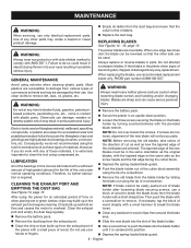
...WARNING: WARNING: Always wear heavy leather gloves and use recommended replacement blade only, RYOBI part number 039821001057. NOTE: Do not over-loosen the screws. Most plastics are reversible. After using the planer for the life of debris. Clean the exhaust port and empty the dust ... blade guard. 8 - Then push the blade with the provided blade wrench. If the blades in pairs. GENERAL MAINTENANCE The planer blades are susceptible to accelerated wear and possible premature failure because the fiberglass chips and grindings are sharp and can be damaged by...
...WARNING: WARNING: Always wear heavy leather gloves and use recommended replacement blade only, RYOBI part number 039821001057. NOTE: Do not over-loosen the screws. Most plastics are reversible. After using the planer for the life of debris. Clean the exhaust port and empty the dust ... blade guard. 8 - Then push the blade with the provided blade wrench. If the blades in pairs. GENERAL MAINTENANCE The planer blades are susceptible to accelerated wear and possible premature failure because the fiberglass chips and grindings are sharp and can be damaged by...
Operation Manual
Page 9
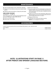
When replacing the belt, use the recommended replacement belt only, RYOBI part number 039821001042. Remove the battery pack. Remove belt cover screws. Remove the belt cover. Force the old belt from both ... to change the other blade. As you turn the belt, pull and work it onto the large pulley until it is in the direction shown. Planer Blades...039821001057 Belt...039821001042 NOTE: ILLUSTRATIONS START ON PAGE 11 AFTER FRENCH AND SPANISH LANGUAGE SECTIONS. 9 - REPLACING THE BELT See Figures 17 - 18, page 13...
When replacing the belt, use the recommended replacement belt only, RYOBI part number 039821001042. Remove the battery pack. Remove belt cover screws. Remove the belt cover. Force the old belt from both ... to change the other blade. As you turn the belt, pull and work it onto the large pulley until it is in the direction shown. Planer Blades...039821001057 Belt...039821001042 NOTE: ILLUSTRATIONS START ON PAGE 11 AFTER FRENCH AND SPANISH LANGUAGE SECTIONS. 9 - REPLACING THE BELT See Figures 17 - 18, page 13...
Parts Diagram
Page 3
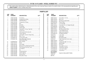
Always mention the model number in all correspondence regarding your HAND PLANER or when ordering repair parts. PARTS LIST KEY PART NO. RYOBI 18 V PLANER - NUMBER DESCRIPTION QTY 1 039821001002 Front Shoe 1 2 039821001003 Compression Spring 1 3 039821001004 Steel Ball (Ø3.5 2 4 039821001005 Compression Spring 2 5 019700001024 Dial 1 6 ...Lock-out Actuator 1 019700001010 Cover Piece 4 NOT SHOWN: 995000058 Operator's Manual (961152665) 12-20-16 (Rev:01) 3 MODEL NUMBER P611 The model number will be found on a label attached to the motor housing.
Always mention the model number in all correspondence regarding your HAND PLANER or when ordering repair parts. PARTS LIST KEY PART NO. RYOBI 18 V PLANER - NUMBER DESCRIPTION QTY 1 039821001002 Front Shoe 1 2 039821001003 Compression Spring 1 3 039821001004 Steel Ball (Ø3.5 2 4 039821001005 Compression Spring 2 5 019700001024 Dial 1 6 ...Lock-out Actuator 1 019700001010 Cover Piece 4 NOT SHOWN: 995000058 Operator's Manual (961152665) 12-20-16 (Rev:01) 3 MODEL NUMBER P611 The model number will be found on a label attached to the motor housing.
Parts Diagram
Page 4
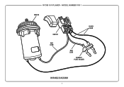
RYOBI 18 V PLANER - MODEL NUMBER P611 MOTOR SWITCH RED LEAD BLACK LEAD RED LEAD CONTACT PLATE HOLDER WIRING DIAGRAM 4
RYOBI 18 V PLANER - MODEL NUMBER P611 MOTOR SWITCH RED LEAD BLACK LEAD RED LEAD CONTACT PLATE HOLDER WIRING DIAGRAM 4


