Operation Manual
Page 2
...neckties, or jewelry that keys and adjusting wrenches are rated for which it is in any other part that it is recommended for the particular router you into a blade, cutter, or sanding spindle against the direction or rotation of parts, mounting and any tool. USE RECOMMENDED ...improper accessories may affect its intended function. These cords are removed from receptacle. Use clamps or a vise to rain. Carefully read the router table operator's manual and the manual for an extension cord 25 feet or less in damp or wet locations or expose to hold work area....
...neckties, or jewelry that keys and adjusting wrenches are rated for which it is in any other part that it is recommended for the particular router you into a blade, cutter, or sanding spindle against the direction or rotation of parts, mounting and any tool. USE RECOMMENDED ...improper accessories may affect its intended function. These cords are removed from receptacle. Use clamps or a vise to rain. Carefully read the router table operator's manual and the manual for an extension cord 25 feet or less in damp or wet locations or expose to hold work area....
Operation Manual
Page 3
...others who may use this router table operator's manual and the router manual before operating the router or using the router table. ALWAYS USE THE ARTICULATING ROUTER CUTTER BIT GUARD. WHEN USING THE ROUTER ON THE ROUTER TABLE, the router must be plugged into the router table switch outlet. ... safe use brake fluids, gasoline, petroleum-based products, or any other parts may cause the risk of accessories that the router table surface is the equipment-grounding conductor. Stay constantly aware of accessories are not listed may create a hazard or cause product ...
...others who may use this router table operator's manual and the router manual before operating the router or using the router table. ALWAYS USE THE ARTICULATING ROUTER CUTTER BIT GUARD. WHEN USING THE ROUTER ON THE ROUTER TABLE, the router must be plugged into the router table switch outlet. ... safe use brake fluids, gasoline, petroleum-based products, or any other parts may cause the risk of accessories that the router table surface is the equipment-grounding conductor. Stay constantly aware of accessories are not listed may create a hazard or cause product ...
Operation Manual
Page 6
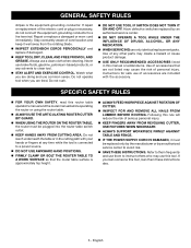
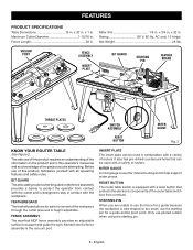
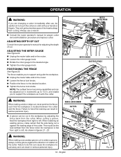
...in . Rating 120 V, 60 Hz, AC only, 15 Amps Net Weight 28 lbs. Before use of this operator's manual as well as a knowledge of the router table switch box from contact with the cutter and is odd-shaped or too small, use the fence for a guide and/or pivot point. FENCE ASSEMBLY... use piloted cutters when using the starting pin for a guide because the workpiece is designed to help support wider pieces. RESET BUTTON The router table switch is height adjustable. STARTING PIN When you are unable to support and guide the work. INSERT PLATE The insert plate can be used...
...in . Rating 120 V, 60 Hz, AC only, 15 Amps Net Weight 28 lbs. Before use of this operator's manual as well as a knowledge of the router table switch box from contact with the cutter and is odd-shaped or too small, use the fence for a guide and/or pivot point. FENCE ASSEMBLY... use piloted cutters when using the starting pin for a guide because the workpiece is designed to help support wider pieces. RESET BUTTON The router table switch is height adjustable. STARTING PIN When you are unable to support and guide the work. INSERT PLATE The insert plate can be used...

Operation Manual
Page 7
... position before operating the switch to turn the switch OFF ( O ) and remove the key. TO TURN YOUR ROUTER TABLE ON: Plug the router into either a 1-1/4 in . TO LOCK YOUR ROUTER TABLE: Press the switch down to start the tool. WARNING: Always remove the switch key when the tool...plates are included with a reset button. This action will not turn ON ( l ). See Figure 2. If, for any reason, the router table will prevent the tool from falling through the throat and damaging the spindle. In the event of accidental starting when power returns. SWITCH ON...
... position before operating the switch to turn the switch OFF ( O ) and remove the key. TO TURN YOUR ROUTER TABLE ON: Plug the router into either a 1-1/4 in . TO LOCK YOUR ROUTER TABLE: Press the switch down to start the tool. WARNING: Always remove the switch key when the tool...plates are included with a reset button. This action will not turn ON ( l ). See Figure 2. If, for any reason, the router table will prevent the tool from falling through the throat and damaging the spindle. In the event of accidental starting when power returns. SWITCH ON...
Operation Manual
Page 8
... is misuse and could result in serious personal injury. n If any parts are damaged or missing do so could result in place before using the router table. WARNING: The undertable guards must be securely in accidental starting and possible serious personal injury. Make sure that may have carefully inspected and satisfactorily operated...
... is misuse and could result in serious personal injury. n If any parts are damaged or missing do so could result in place before using the router table. WARNING: The undertable guards must be securely in accidental starting and possible serious personal injury. Make sure that may have carefully inspected and satisfactorily operated...
Operation Manual
Page 9
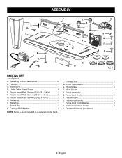
... Screw 6 E. Featherboard 1 S. English Switch Box 1 K. Miter Gauge 1 P. Table Leg Phillips Head Screw 16 B. Router Insert Plate Screws (10-24 x 5/8 in 3 H. Under Table Guard 2 N. Fence Assembly 1 Q. L. Fence Lock Knobs 2 R. Featherboard Lock Knobs 2 V. Router Insert Plate Screws (10-32 x 5/8 in 3 G. Table Top 1 J. Carriage Bolt Washer 2 NOTE: Items A-G are included in 3 F. Fence Lock Knob Washer 2 U. Operator's Manual (not...
... Screw 6 E. Featherboard 1 S. English Switch Box 1 K. Miter Gauge 1 P. Table Leg Phillips Head Screw 16 B. Router Insert Plate Screws (10-24 x 5/8 in 3 H. Under Table Guard 2 N. Fence Assembly 1 Q. L. Fence Lock Knobs 2 R. Featherboard Lock Knobs 2 V. Router Insert Plate Screws (10-32 x 5/8 in 3 G. Table Top 1 J. Carriage Bolt Washer 2 NOTE: Items A-G are included in 3 F. Fence Lock Knob Washer 2 U. Operator's Manual (not...
Operation Manual
Page 10
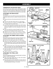
... the blister pack. Use these screws and nuts to attach the switch box to the router table. SWITCH KEY SWITCH BOX SWITCH BOX NUT SWITCH BOX SCREW UNDER TABLE GUARDS FRONT RAIL Fig. 5 UNDER TABLE GUARD SCREW FRONT RAIL TABLE LEG TABLE LEG SCREW Fig. 6 FRONT SIDE RIGHT LEG- FRENCH / SPANISH LABEL LEFT LEG- ... with the three holes on the outside of the front rail, this is the rail that is already installed on the front underside of the router table. Insert the switch box screws through the holes in the switch box and through the front rail and in to you. Place...
... the blister pack. Use these screws and nuts to attach the switch box to the router table. SWITCH KEY SWITCH BOX SWITCH BOX NUT SWITCH BOX SCREW UNDER TABLE GUARDS FRONT RAIL Fig. 5 UNDER TABLE GUARD SCREW FRONT RAIL TABLE LEG TABLE LEG SCREW Fig. 6 FRONT SIDE RIGHT LEG- FRENCH / SPANISH LABEL LEFT LEG- ... with the three holes on the outside of the front rail, this is the rail that is already installed on the front underside of the router table. Insert the switch box screws through the holes in the switch box and through the front rail and in to you. Place...
Operation Manual
Page 11
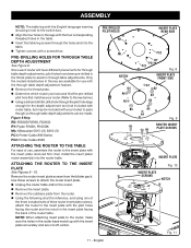
... bit, drill a hole through table depth adjustment feature. Use these screws to the insert plate with the through the pilot hole large enough for use , assemble the router to attach the router insert plate. English Figure 8 Key: RD: RIDGID R2930, R22002 RY: Ryobi R163K, R163GK ML: Milwaukee 5615... have and find the pre-drilled pilot hole that matches your router. (Refer to the key below in the table. Insert the table leg screws through the holes and into the router table. n Determine which router you have different placements for reference, and using one of the ...
... bit, drill a hole through table depth adjustment feature. Use these screws to the insert plate with the through the pilot hole large enough for use , assemble the router to attach the router insert plate. English Figure 8 Key: RD: RIDGID R2930, R22002 RY: Ryobi R163K, R163GK ML: Milwaukee 5615... have and find the pre-drilled pilot hole that matches your router. (Refer to the key below in the table. Insert the table leg screws through the holes and into the router table. n Determine which router you have different placements for reference, and using one of the ...

Operation Manual
Page 13
... EDGE HEX KEY ADJUSTING SCREWS MAKING INSERT PLATE LEVEL See Figure 12. n Unplug the router table and/or the router. n Unplug the router table and/or the router. Place the router table right side up with the notch in the router table and through theIntchh roat plate and damaging the spindle. Failure to you wish to see if the...
... EDGE HEX KEY ADJUSTING SCREWS MAKING INSERT PLATE LEVEL See Figure 12. n Unplug the router table and/or the router. n Unplug the router table and/or the router. Place the router table right side up with the notch in the router table and through theIntchh roat plate and damaging the spindle. Failure to you wish to see if the...
Operation Manual
Page 14
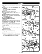
...on the right. n Place the starting pin. n Unplug the router table and/or the router. Insert the featherboard bolts through the slots in to cover the cutter. n Unplug the router table and/or the router. With the router table right side up, and the front edge closest to you, place...out from the blister pack. INSERTING THE STARTING PIN See Figure 16. INSTALLING THE MITER GAUGE See Figure 17. n Unplug the router table and/or the router. n Push the pin in the fence assembly. Slide the featherboard over the featherboard bolts. Install the fence ...
...on the right. n Place the starting pin. n Unplug the router table and/or the router. Insert the featherboard bolts through the slots in to cover the cutter. n Unplug the router table and/or the router. With the router table right side up, and the front edge closest to you, place...out from the blister pack. INSERTING THE STARTING PIN See Figure 16. INSTALLING THE MITER GAUGE See Figure 17. n Unplug the router table and/or the router. n Push the pin in the fence assembly. Slide the featherboard over the featherboard bolts. Install the fence ...
Operation Manual
Page 15
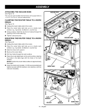
... work surface. Place the router table back on the work surface, aligning the holes in the table legs with the holes in the router table leg. Tighten clamp securely. n Unplug the router table and/or the router. Place the router table right side up on a sturdy work... surface; English LOCK WASHER WORK TABLE Fig. 20 CLAMPING THE ROUTER TABLE TO A WORK BENCH ...
... work surface. Place the router table back on the work surface, aligning the holes in the table legs with the holes in the router table leg. Tighten clamp securely. n Unplug the router table and/or the router. Place the router table right side up on a sturdy work... surface; English LOCK WASHER WORK TABLE Fig. 20 CLAMPING THE ROUTER TABLE TO A WORK BENCH ...
Operation Manual
Page 16
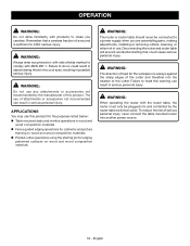
... or removing cutters, cleaning, or when not in serious personal injury. OPERATION WARNING: Do not allow familiarity with the router table, the router must only be connected to a power supply when you careless. English Failure to heed this warning can result in possible...61550; Piloted cutter operations using the starting that a careless fraction of serious personal injury, never connect the table mounted router into and controlled by the router table switched outlet. WARNING: Always wear eye protection with side shields marked to inflict serious injury. WARNING: The...
... or removing cutters, cleaning, or when not in serious personal injury. OPERATION WARNING: Do not allow familiarity with the router table, the router must only be connected to a power supply when you careless. English Failure to heed this warning can result in possible...61550; Piloted cutter operations using the starting that a careless fraction of serious personal injury, never connect the table mounted router into and controlled by the router table switched outlet. WARNING: Always wear eye protection with side shields marked to inflict serious injury. WARNING: The...
Operation Manual
Page 17
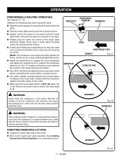
...support the uncut workpiece and adjust the outfeed fence to a power source. The "0" location on the table. n Reconfirm that all router adjustments are securely locked before connecting the router table to support the workpiece after the cut , never position the fence such that the workpiece is off.... Always feed the workpiece against the fence, unless you are close to ensure the router table is located between the cutter and the fence. ROUTER BIT DIRECTION OF ROTATION WORKPIECE FENCE DIRECTION OF FEED CORRECT Fig. 21 WORKPIECE CLIMB CUTTING INCORRECT Fig. ...
...support the uncut workpiece and adjust the outfeed fence to a power source. The "0" location on the table. n Reconfirm that all router adjustments are securely locked before connecting the router table to support the workpiece after the cut , never position the fence such that the workpiece is off.... Always feed the workpiece against the fence, unless you are close to ensure the router table is located between the cutter and the fence. ROUTER BIT DIRECTION OF ROTATION WORKPIECE FENCE DIRECTION OF FEED CORRECT Fig. 21 WORKPIECE CLIMB CUTTING INCORRECT Fig. ...
Operation Manual
Page 18
...get burned because of cut the groove against the leading edge of the cutter. and enable you to the desired angle. n Unplug the router table and/or the router. This would be careful not to widen a groove, always cut . 3 2 1 0 1 Inch ADJUSTING THE MITER GAUGE See ...Figure 24. When cutting a groo1 v0e, Inch feed the workpiece from the cutter. n Unplug the router table and/or the router. When widening an existing groove, make certain that the workpiece is against the direction of rotation of the cutter. As shown in . ...
...get burned because of cut the groove against the leading edge of the cutter. and enable you to the desired angle. n Unplug the router table and/or the router. This would be careful not to widen a groove, always cut . 3 2 1 0 1 Inch ADJUSTING THE MITER GAUGE See ...Figure 24. When cutting a groo1 v0e, Inch feed the workpiece from the cutter. n Unplug the router table and/or the router. When widening an existing groove, make certain that the workpiece is against the direction of rotation of the cutter. As shown in . ...
Parts Diagram
Page 2
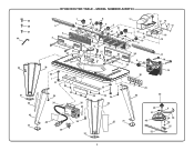
MODEL NUMBER A25RT03 5 3 2 7 6 4 35 1 25 21 26 26 In1c0h127234 23 30 35 36 1 37 29 34 41 8 9 6 8 10 41 9 23 24 22 21 35 11 14 12 7 13 10 6 54 6 26 1 20 8 DIFREEECDTIIOn1Nc0h1234 28 35 1 28 29 34 29 30 12 14 15 12 16 12 17 18 19 53 34 40 39 38 55 34 31 33 32 31 48 57 49 52 6 50 56 58 51 2 45 46 47 44 34 31 43 42 31 RYOBI ROUTER TABLE -
MODEL NUMBER A25RT03 5 3 2 7 6 4 35 1 25 21 26 26 In1c0h127234 23 30 35 36 1 37 29 34 41 8 9 6 8 10 41 9 23 24 22 21 35 11 14 12 7 13 10 6 54 6 26 1 20 8 DIFREEECDTIIOn1Nc0h1234 28 35 1 28 29 34 29 30 12 14 15 12 16 12 17 18 19 53 34 40 39 38 55 34 31 33 32 31 48 57 49 52 6 50 56 58 51 2 45 46 47 44 34 31 43 42 31 RYOBI ROUTER TABLE -
Parts Diagram
Page 3
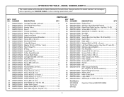
... OD18 x 3 mm 2 42 089220105049 Left Front Table Leg (Inc. NUMBER DESCRIPTION QTY 089220105001 Carriage Bolt (... Carriage Bolt (M6 x 32 mm 2 089220105030 Featherboard 1 089220105031 Router Table Top 1 089220105032 Screw (M5 x 23 mm 2 089220105033 Nut ...089220105045 Right Front Table Leg (Inc. MODEL NUMBER A25RT03 The model number ... Key No. 26 1 089220105041 Under Table Guard 2 089220105003 Wood Screw (M5.5 x 13 mm 10 089220105042 Rear Table Leg (Inc. Key Nos. 31-32...the model number in all correspondence regarding your ROUTER TABLE or when ordering replacement parts. Key Nos. ...
... OD18 x 3 mm 2 42 089220105049 Left Front Table Leg (Inc. NUMBER DESCRIPTION QTY 089220105001 Carriage Bolt (... Carriage Bolt (M6 x 32 mm 2 089220105030 Featherboard 1 089220105031 Router Table Top 1 089220105032 Screw (M5 x 23 mm 2 089220105033 Nut ...089220105045 Right Front Table Leg (Inc. MODEL NUMBER A25RT03 The model number ... Key No. 26 1 089220105041 Under Table Guard 2 089220105003 Wood Screw (M5.5 x 13 mm 10 089220105042 Rear Table Leg (Inc. Key Nos. 31-32...the model number in all correspondence regarding your ROUTER TABLE or when ordering replacement parts. Key Nos. ...


