English Manual
Page 5
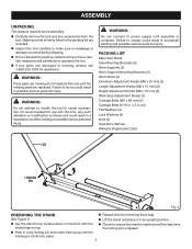
...Figure 2. n Do not discard the packing material until the locking pin clicks into place. 5 Failure to power supply until the missing parts are replaced. Failure to comply could result in a hazardous condition leading to ensure the stand is stable and all items listed in possible ...serious personal injury. n Carefully remove the tool and any parts are missing do so could result in accidental starting and possible serious personal injury. n Lay the stand's top surface down on top. ...
...Figure 2. n Do not discard the packing material until the locking pin clicks into place. 5 Failure to power supply until the missing parts are replaced. Failure to comply could result in a hazardous condition leading to ensure the stand is stable and all items listed in possible ...serious personal injury. n Carefully remove the tool and any parts are missing do so could result in accidental starting and possible serious personal injury. n Lay the stand's top surface down on top. ...
English Manual
Page 8
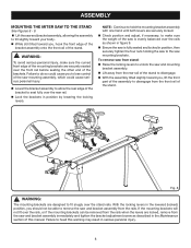
... rear rail. If the mounting brackets will not fit over the stand rails. n Lock the brackets in the lowered (locked) position, you , lift the front part of the assembly to disengage from the front rail of this warning may result in figure 9. To remove saw from stand: n Raise the locking levers...
... rear rail. If the mounting brackets will not fit over the stand rails. n Lock the brackets in the lowered (locked) position, you , lift the front part of the assembly to disengage from the front rail of this warning may result in figure 9. To remove saw from stand: n Raise the locking levers...
English Manual
Page 12
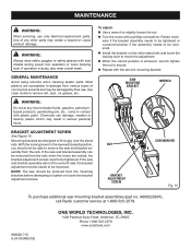
...adjustment screws. With the locking levers in the lowered (locked) position, you should be damaged by their use only identical replacement parts. nut BRACKET ADJUSTMENT SCREW screwdriver Fig. 15 To purchase additional saw and bracket assembly can damage, weaken or destroy plastic which.... n When the correct position is dusty, also wear a dust mask. If the saw should not be tightened. A000220601), call Ryobi customer service at any other parts may create a hazard or cause product damage. bracket ADJUSTMENT SCREW See Figure 15. If the saw mounting bracket assemblies...
...adjustment screws. With the locking levers in the lowered (locked) position, you should be damaged by their use only identical replacement parts. nut BRACKET ADJUSTMENT SCREW screwdriver Fig. 15 To purchase additional saw and bracket assembly can damage, weaken or destroy plastic which.... n When the correct position is dusty, also wear a dust mask. If the saw should not be tightened. A000220601), call Ryobi customer service at any other parts may create a hazard or cause product damage. bracket ADJUSTMENT SCREW See Figure 15. If the saw mounting bracket assemblies...
Repair Sheet
Page 3
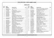
...WARNING LABEL 2 OPERATOR'S MANUAL (9000225330501) REPAIR SHEET (REV:02) * STANDARD HARDWARE ITEM - MAY BE PURCHASED LOCALLY 3 MODEL NUMBER A18MS01 PARTS LIST KEY NO. 1 2 3 4 5 6 7 8 9 10 11 12 13 14 15 16 17 18 19 20 21 22 23 24 25 26 27...37 38 39 40 41 42 43 44 45 46 47 48 49 50 51 52 53 PART NUMBER A000220601 0131010019 0000220216 0000220210 411072001 0000220307-57 9000225330301 0000220211 414012034 0000220212 410132044 410132035 411012004 0000220309 0000220213... (M6 1 REAR CLAMPING JAW PROTECTOR 1 REAR CLAMING JAW 1 FRONT CLAMPING JAW 1 SCREW A (PAN HD. - RYOBI MITER STAND -
...WARNING LABEL 2 OPERATOR'S MANUAL (9000225330501) REPAIR SHEET (REV:02) * STANDARD HARDWARE ITEM - MAY BE PURCHASED LOCALLY 3 MODEL NUMBER A18MS01 PARTS LIST KEY NO. 1 2 3 4 5 6 7 8 9 10 11 12 13 14 15 16 17 18 19 20 21 22 23 24 25 26 27...37 38 39 40 41 42 43 44 45 46 47 48 49 50 51 52 53 PART NUMBER A000220601 0131010019 0000220216 0000220210 411072001 0000220307-57 9000225330301 0000220211 414012034 0000220212 410132044 410132035 411012004 0000220309 0000220213... (M6 1 REAR CLAMPING JAW PROTECTOR 1 REAR CLAMING JAW 1 FRONT CLAMPING JAW 1 SCREW A (PAN HD. - RYOBI MITER STAND -


