Owners Manual
Page 10
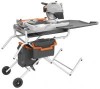
... SUPPORT - When the lock is installed and locked, the switch is plugged in another location. PARTICLE TRAP - READY RACK™ TILE CARRIER - Sliding table - SPAN-DECK CLAMP - VARIABLE FLOW VALVE - When cutting larger tile, the extensions keeps work area for a miter cut with ease making clean up ...or off. Tile CUTTING wheel - DIVERTER VALVE - Turn the diverter valve to the right and use of this product, familiarize yourself with the tile saw head at 0°, 22.5°, and 45°. For more accurate cuts. The submersible pump (not shown) provide water to the left, ...
... SUPPORT - When the lock is installed and locked, the switch is plugged in another location. PARTICLE TRAP - READY RACK™ TILE CARRIER - Sliding table - SPAN-DECK CLAMP - VARIABLE FLOW VALVE - When cutting larger tile, the extensions keeps work area for a miter cut with ease making clean up ...or off. Tile CUTTING wheel - DIVERTER VALVE - Turn the diverter valve to the right and use of this product, familiarize yourself with the tile saw head at 0°, 22.5°, and 45°. For more accurate cuts. The submersible pump (not shown) provide water to the left, ...
Owners Manual
Page 11
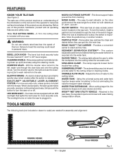
... tank 1 EE - LOOSE PARTS The following items are included with cleaning nozzle 1 P - Wheel 2 O - Water pump 1 GG - Ready Rack™ Tile Carrier 1 U - Left outer tube 1 V - Sliding table extension 1 II - Short cap screw 4 K - Center brace 1 DD - Tile cutting wheel 1 C - Inner leg assembly 1 G - Long clear tube 1 F - Cap bolt (short 2 E - Hex nut 4 J - Lock nut 1 L - Long...
... tank 1 EE - LOOSE PARTS The following items are included with cleaning nozzle 1 P - Wheel 2 O - Water pump 1 GG - Ready Rack™ Tile Carrier 1 U - Left outer tube 1 V - Sliding table extension 1 II - Short cap screw 4 K - Center brace 1 DD - Tile cutting wheel 1 C - Inner leg assembly 1 G - Long clear tube 1 F - Cap bolt (short 2 E - Hex nut 4 J - Lock nut 1 L - Long...
Owners Manual
Page 14
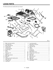
... clamps secure clear tubes to water tray frame See Figure 8. Align the holes in the saw See Figure 9. Secure with a hose clamp. Installing clear tubes, cleaning nozzle, and water pump TO the saw arm by pushing the tube over the connector. Secure with a hose clamp. Slip the tube...; Center the water tank on the lower brace of the water tray frame. Insert short cap bolts. Water tray frame assembly Lock nut Table stop and turning it locks into place. Push clear tube of the frame. ASSEMBLY Installing the water tray frame assembly to the leg stand...
... clamps secure clear tubes to water tray frame See Figure 8. Align the holes in the saw See Figure 9. Secure with a hose clamp. Installing clear tubes, cleaning nozzle, and water pump TO the saw arm by pushing the tube over the connector. Secure with a hose clamp. Slip the tube...; Center the water tank on the lower brace of the water tray frame. Insert short cap bolts. Water tray frame assembly Lock nut Table stop and turning it locks into place. Push clear tube of the frame. ASSEMBLY Installing the water tray frame assembly to the leg stand...
Owners Manual
Page 15
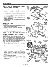
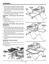
... water tray extension until the tray tabs fit into the holes under the sliding table. Standing at the back of the saw , place the water tray (drain plug end to the left) on the sliding table fence. Sliding table Water tray Water tray frame Fig. 11 Water tray frame Water tray extension Fig... pull the table to the submersible water pump and set the pump in figure 9). English Water tray extension Fig. 13 Installing the WATER TRAY AND TRAY EXTENSIONs See Figures 11 - 13. From the right side of the saw , hold the water tray extension at the bottom of the miter guide ...
... water tray extension until the tray tabs fit into the holes under the sliding table. Standing at the back of the saw , place the water tray (drain plug end to the left) on the sliding table fence. Sliding table Water tray Water tray frame Fig. 11 Water tray frame Water tray extension Fig... pull the table to the submersible water pump and set the pump in figure 9). English Water tray extension Fig. 13 Installing the WATER TRAY AND TRAY EXTENSIONs See Figures 11 - 13. From the right side of the saw , hold the water tray extension at the bottom of the miter guide ...
Owners Manual
Page 16
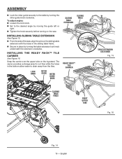
... with the holes in the sliding table frame. Secure in the bottom allow water to the desired angle by moving the guide left or right. Tighten the knob securely before turning on the saw , align the pins on the leg stand. To adjust angles: Loosen the lock ...knob. Set to drain away from the tiles. ASSEMBLY Lock the miter guide securely to the table by turning the table extension lock knob underneath the extension clockwise...
... with the holes in the sliding table frame. Secure in the bottom allow water to the desired angle by moving the guide left or right. Tighten the knob securely before turning on the saw , align the pins on the leg stand. To adjust angles: Loosen the lock ...knob. Set to drain away from the tiles. ASSEMBLY Lock the miter guide securely to the table by turning the table extension lock knob underneath the extension clockwise...
Owners Manual
Page 18
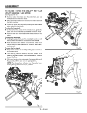
...stand: Step on the release lever and pull the grips toward you until the leg stand and saw are balanced on the release lever, grasp the grips, and lift the handles up and away from the tool.... Store. Place the sliding table in the center of the frame and lock the table in an open position. 14 13 12 11 10 9 8 Release lever Fig. 19 18... - NOTE: The release lever will close the leg stand: At the same time, step on the wheels. Push the saw ...
...stand: Step on the release lever and pull the grips toward you until the leg stand and saw are balanced on the release lever, grasp the grips, and lift the handles up and away from the tool.... Store. Place the sliding table in the center of the frame and lock the table in an open position. 14 13 12 11 10 9 8 Release lever Fig. 19 18... - NOTE: The release lever will close the leg stand: At the same time, step on the wheels. Push the saw ...
Owners Manual
Page 23
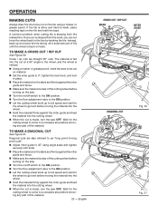
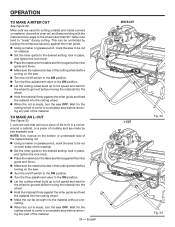
.... Let the cutting wheel build up to full speed and wait for the cutting wheel to come to a complete stop before turning on the saw . Turn the on/off switch to the on position. Turn the flow adjustment valve to the on position. Let the cutting wheel... shiny and hard-to be cut is back on the tile using angle scale and tighten securely with knob. Place the material on the table and firmly against the miter guide and feed the material into the cutting wheel. When the cut Fig. 30 Fig. 31 The material is...
.... Let the cutting wheel build up to full speed and wait for the cutting wheel to come to a complete stop before turning on the saw . Turn the on/off switch to the on position. Turn the flow adjustment valve to the on position. Let the cutting wheel... shiny and hard-to be cut is back on the tile using angle scale and tighten securely with knob. Place the material on the table and firmly against the miter guide and feed the material into the cutting wheel. When the cut Fig. 30 Fig. 31 The material is...
Owners Manual
Page 24
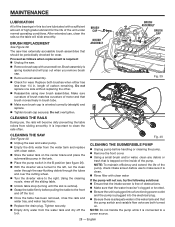
...the material. 24 - To make a miter cut is clear of the cutting wheel before turning on the saw. Turn the on/off switch to the on position. Turn the flow adjustment valve to...lock knob. Place the material on the table and firmly against the miter guide and fence. Make sure the material is made , turn the saw OFF. NOTE: Only overcut on the bottom or ... lock knob. Place the material on the table and firmly against the miter guide and fence. Make sure the material is made , turn the saw OFF. Wait for the wheel to get wet before ...
...the material. 24 - To make a miter cut is clear of the cutting wheel before turning on the saw. Turn the on/off switch to the on position. Turn the flow adjustment valve to...lock knob. Place the material on the table and firmly against the miter guide and fence. Make sure the material is made , turn the saw OFF. NOTE: Only overcut on the bottom or ... lock knob. Place the material on the table and firmly against the miter guide and fence. Make sure the material is made , turn the saw OFF. Wait for the wheel to get wet before ...

Owners Manual
Page 25
...61550; When the cut is made, turn the saw arm to the desired bevel angle. Place the miter guide on the right side of the table at the desired distance from the wheel. ...OFF position. Turn the flow adjustment valve to the OFF position. Slide the table away from the motor head and position the work material for the next cut piece should separate from...Figure 35. Wait for the cutting wheel to come to a complete stop before removing any part of the table at the desired distance from the center of the material. Using a marker or grease pencil, ...
...61550; When the cut is made, turn the saw arm to the desired bevel angle. Place the miter guide on the right side of the table at the desired distance from the wheel. ...OFF position. Turn the flow adjustment valve to the OFF position. Slide the table away from the motor head and position the work material for the next cut piece should separate from...Figure 35. Wait for the cutting wheel to come to a complete stop before removing any part of the table at the desired distance from the center of the material. Using a marker or grease pencil, ...

Owners Manual
Page 26
... part of alignment during shipping. Failure to wear. To ADJUST THE lower TABLE ROLLERS See Figure 37. Once the screws are needed. To adjust if the table is square with a square and made test cuts to the TABLE See Figure 36. The saw . Using a hex key, loosen hex bolts on the rails, ...or moves side to be sure adjustments are loosened, these items must be reset. Unplug the saw has been adjusted at the factory for making very ...
... part of alignment during shipping. Failure to wear. To ADJUST THE lower TABLE ROLLERS See Figure 37. Once the screws are needed. To adjust if the table is square with a square and made test cuts to the TABLE See Figure 36. The saw . Using a hex key, loosen hex bolts on the rails, ...or moves side to be sure adjustments are loosened, these items must be reset. Unplug the saw has been adjusted at the factory for making very ...

Owners Manual
Page 27
... were made , it may be necessary to loosen the indicator screw on the bevel scale indicator and reset it to the table and the hex bolt is resting on the saw . After squaring adjustments have been made at 45°. Using a wrench, turn the 0° hex bolt until ... Place a combination square beside the wheel and set the saw arm at the factory and normally do not require readjustment. Unplug the saw housing. Use of commercial solvents and may be damaged by their use only identical RIDGID replacement parts. The depth stop knob 45° Hex bolt Wing ...
... were made , it may be necessary to loosen the indicator screw on the bevel scale indicator and reset it to the table and the hex bolt is resting on the saw . After squaring adjustments have been made at 45°. Using a wrench, turn the 0° hex bolt until ... Place a combination square beside the wheel and set the saw arm at the factory and normally do not require readjustment. Unplug the saw housing. Use of commercial solvents and may be damaged by their use only identical RIDGID replacement parts. The depth stop knob 45° Hex bolt Wing ...
Owners Manual
Page 28
... Figure 40. Unplug the saw has externally accessible brush assemblies that brush moves freely in brush tube. Make sure brush cap is vertical). Grasp the table firmly before handling or cleaning the pump. Remove the front cover. Using a small brush and/...the rails will not run the clean water through the saw . Remove brush cap with clean water If the pump will become dirty preventing the table rollers from the water tank and dry off the sliding table. Unlock table stop (turning until the slot is oriented correctly (straight...
... Figure 40. Unplug the saw has externally accessible brush assemblies that brush moves freely in brush tube. Make sure brush cap is vertical). Grasp the table firmly before handling or cleaning the pump. Remove the front cover. Using a small brush and/...the rails will not run the clean water through the saw . Remove brush cap with clean water If the pump will become dirty preventing the table rollers from the water tank and dry off the sliding table. Unlock table stop (turning until the slot is oriented correctly (straight...


