
Operation Manual
Page 10
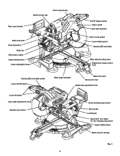
...-lock lever Bevel-lock lever Depth stop adjustment bolt Crown molding stop button Bevel scale Locking pin Bevel 33.9° (for USA)/ 30° (for Canada) stop block Upper sliding fence Blade wrench storage Fig. 1 9
...-lock lever Bevel-lock lever Depth stop adjustment bolt Crown molding stop button Bevel scale Locking pin Bevel 33.9° (for USA)/ 30° (for Canada) stop block Upper sliding fence Blade wrench storage Fig. 1 9
Operation Manual
Page 11
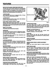
... with a 10-inch Freud 40-tooth, general purpose blade. POSITIVE STOPS ON MITER TABLE Positive stops at bevel 33.9° (USA)/ 30° (Canada). wrenches The larger blade wrench is used for laser adjustment and for changing the blade. To cut flat wood stock. 10 Bevel-lock lever To...used with the miterlock lever lifted (unlocked), can also be turned to different angles along the X-axis and Y-axis. The storage area for Canada). It retracts over the upper blade guard as knowledge of the project you are located on the work piece. SLIDE-LOCK KNOB The slide-lock...
... with a 10-inch Freud 40-tooth, general purpose blade. POSITIVE STOPS ON MITER TABLE Positive stops at bevel 33.9° (USA)/ 30° (Canada). wrenches The larger blade wrench is used for laser adjustment and for changing the blade. To cut flat wood stock. 10 Bevel-lock lever To...used with the miterlock lever lifted (unlocked), can also be turned to different angles along the X-axis and Y-axis. The storage area for Canada). It retracts over the upper blade guard as knowledge of the project you are located on the work piece. SLIDE-LOCK KNOB The slide-lock...
Operation Manual
Page 17
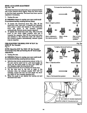
...the operator To tighten the bevel-lock lever Fig. 16a Step 5. Lift Fig. 16b Locking nut 33.9° (USA)/ 30° (Canada) stopping bolt Bevel 33.9° (USA)/ 30° (Canada) stop block 180°. 3. Bevel-Lock Lever Adjustment Fig. 16a - 16b The bevel-lock lever securely locks your compound miter saw...-lock lever will return to release the bevel-lock. 4. When the angle is set the bevel angle to 33.9° (for USA)/ 30° (for Canada), rotate the stop block Fig. 17 16 Lift Step 5. Pull it . Press down to a 45° bevel angle. If the indicator does not indicate exactly...
...the operator To tighten the bevel-lock lever Fig. 16a Step 5. Lift Fig. 16b Locking nut 33.9° (USA)/ 30° (Canada) stopping bolt Bevel 33.9° (USA)/ 30° (Canada) stop block 180°. 3. Bevel-Lock Lever Adjustment Fig. 16a - 16b The bevel-lock lever securely locks your compound miter saw...-lock lever will return to release the bevel-lock. 4. When the angle is set the bevel angle to 33.9° (for USA)/ 30° (for Canada), rotate the stop block Fig. 17 16 Lift Step 5. Pull it . Press down to a 45° bevel angle. If the indicator does not indicate exactly...
Operation Manual
Page 18
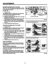
...; (for adjusting the left stop plate Fig. 18b 17 ADJUSTING THE BEVEL STOP TO 48° RIGHT 1. Rotate the bevel 33.9° (USA)/ 30° (Canada) stop block out of the way. 4. Hold the saw-arm and tilt it a few degrees to the left so that the 48° to bevel... adjustments were made at the factory and, under normal circumstances, they do not require re-adjustment. one for adjusting the right bevel and one for Canada) stop block out of the way. 4. Press and hold down the right bevel range control lever; Saw-arm Travel Pivot Adjustment: The saw arm should...
...; (for adjusting the left stop plate Fig. 18b 17 ADJUSTING THE BEVEL STOP TO 48° RIGHT 1. Rotate the bevel 33.9° (USA)/ 30° (Canada) stop block out of the way. 4. Hold the saw-arm and tilt it a few degrees to the left so that the 48° to bevel... adjustments were made at the factory and, under normal circumstances, they do not require re-adjustment. one for adjusting the right bevel and one for Canada) stop block out of the way. 4. Press and hold down the right bevel range control lever; Saw-arm Travel Pivot Adjustment: The saw arm should...
Operation Manual
Page 23
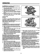
.... 9. Unplug the saw. � WARNING: Failure to complete the cut. 10. If the concave edge of the "No-Hands Zone", as an additional support for Canada) left or right by lowering the saw arm to any cutting operation "freehand" (i.e., without holding the work piece against the fence), because the blade could...
.... 9. Unplug the saw. � WARNING: Failure to complete the cut. 10. If the concave edge of the "No-Hands Zone", as an additional support for Canada) left or right by lowering the saw arm to any cutting operation "freehand" (i.e., without holding the work piece against the fence), because the blade could...

Operation Manual
Page 26
... result in scrap material before making a cut. To set from the blade. When cutting a long work piece, use another person as an additional support for Canada) left (pull out the stop rotating before raising the blade out of the work piece with a pencil. 3. Also, never perform any cutting operation "freehand" (i.e.; without...
... result in scrap material before making a cut. To set from the blade. When cutting a long work piece, use another person as an additional support for Canada) left (pull out the stop rotating before raising the blade out of the work piece with a pencil. 3. Also, never perform any cutting operation "freehand" (i.e.; without...

Operation Manual
Page 30
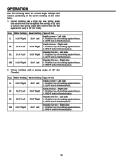
.... When cutting crown molding, the bevel angle should be set at 33.9° (for USA)/ 30° (for Canada), the miter angle should be set at 31.6° (for USA) / 35.3° (for Canada) either left or right, depending on scrap molding. Left side LEFT side is finished piece. 0° Inside Corner...
.... When cutting crown molding, the bevel angle should be set at 33.9° (for USA)/ 30° (for Canada), the miter angle should be set at 31.6° (for USA) / 35.3° (for Canada) either left or right, depending on scrap molding. Left side LEFT side is finished piece. 0° Inside Corner...
Operation Manual
Page 31
... is finished piece. 2. OPERATION See the following table for correct angle settings and correct positioning of molding against fence. 2. Position top of 45° (for Canada). Right side 1. Left side 1. Right side IR 35.3° Left 30.0° Right 1. LEFT side is finished piece. LEFT side is finished piece. Position top...
... is finished piece. 2. OPERATION See the following table for correct angle settings and correct positioning of molding against fence. 2. Position top of 45° (for Canada). Right side 1. Left side 1. Right side IR 35.3° Left 30.0° Right 1. LEFT side is finished piece. LEFT side is finished piece. Position top...