
English Manual
Page 2
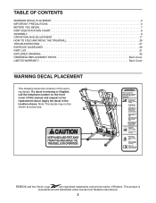
... CONTENTS WARNING DECAL PLACEMENT 2 IMPORTANT PRECAUTIONS 3 BEFORE YOU BEGIN 7 PART IDENTIFICATION CHART 8 ASSEMBLY 9 OPERATION AND ADJUSTMENT 17 HOW TO FOLD AND MOVE THE TREADMILL 26 TROUBLESHOOTING 27 EXERCISE GUIDELINES 30 PART LIST 31 EXPLODED DRAWING 32 ORDERING REPLACEMENT PARTS Back Cover...WARNING DECAL PLACEMENT This drawing shows the locations of Reebok. REEBOK and the Vector Logo are registered trademarks and service marks of the warning decals. If a decal is manufactured and distributed under license from Reebok International. 2 This product is missing or illegible,...
... CONTENTS WARNING DECAL PLACEMENT 2 IMPORTANT PRECAUTIONS 3 BEFORE YOU BEGIN 7 PART IDENTIFICATION CHART 8 ASSEMBLY 9 OPERATION AND ADJUSTMENT 17 HOW TO FOLD AND MOVE THE TREADMILL 26 TROUBLESHOOTING 27 EXERCISE GUIDELINES 30 PART LIST 31 EXPLODED DRAWING 32 ORDERING REPLACEMENT PARTS Back Cover...WARNING DECAL PLACEMENT This drawing shows the locations of Reebok. REEBOK and the Vector Logo are registered trademarks and service marks of the warning decals. If a decal is manufactured and distributed under license from Reebok International. 2 This product is missing or illegible,...
English Manual
Page 4
... drawing on page 7 for the location of the treadmill regularly. 20. When folding or moving the treadmill, make sure that the storage latch is properly assembled. (See ASSEMBLY on page 9 and HOW TO FOLD AND MOVE THE TREADMILL on the treadmill. 26. DANGER: 27. Never remove the motor hood... unless instructed to move the treadmill until it is not a medical ...
... drawing on page 7 for the location of the treadmill regularly. 20. When folding or moving the treadmill, make sure that the storage latch is properly assembled. (See ASSEMBLY on page 9 and HOW TO FOLD AND MOVE THE TREADMILL on the treadmill. 26. DANGER: 27. Never remove the motor hood... unless instructed to move the treadmill until it is not a medical ...
English Manual
Page 8
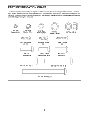
... PART LIST near the end of this manual. Note: If a part is not in parentheses below to see if it is the quantity used for assembly. The number following the key number is preattached. Extra parts may be included. #10 Star Washer (12)–-4 1/4" Star Washer (11)–-4 5/16" Star Washer... Head Screw (4)–-4 5/16" x 1" Bolt (5)–-2 3/8" x 2" Bolt (2)–-2 3/8" x 2 1/2" Bolt (7)–-2 3/8" x 4" Screw (3)–-6 8 The number in the hardware kit, check to identify small parts used for assembly.
... PART LIST near the end of this manual. Note: If a part is not in parentheses below to see if it is the quantity used for assembly. The number following the key number is preattached. Extra parts may be included. #10 Star Washer (12)–-4 1/4" Star Washer (11)–-4 5/16" Star Washer... Head Screw (4)–-4 5/16" x 1" Bolt (5)–-2 3/8" x 2" Bolt (2)–-2 3/8" x 2 1/2" Bolt (7)–-2 3/8" x 4" Screw (3)–-6 8 The number in the hardware kit, check to identify small parts used for assembly.
English Manual
Page 9
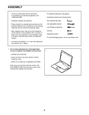
... Internet access, call 1-800-445-2480. •• Assembly requires two persons. •• Place all assembly steps. •• After shipping, there may be an oily substance on the exterior of the treadmill. This is an oily substance on the treadmill, wipe it off with a soft cloth and a mild,...front cover of this manual) and register your product. 9 Do not dispose of the packing materials until you do not use power tools. 1. ASSEMBLY •• To hire an authorized service technician to notify you of upgrades and offers Note: If you nish all parts in a ...
... Internet access, call 1-800-445-2480. •• Assembly requires two persons. •• Place all assembly steps. •• After shipping, there may be an oily substance on the exterior of the treadmill. This is an oily substance on the treadmill, wipe it off with a soft cloth and a mild,...front cover of this manual) and register your product. 9 Do not dispose of the packing materials until you do not use power tools. 1. ASSEMBLY •• To hire an authorized service technician to notify you of upgrades and offers Note: If you nish all parts in a ...

English Manual
Page 13
Set the console assembly face down on a soft surface to the Handrails (76, 77) with four #10 x 3/4" Screws (6) and four #10 Star Washers (12); Then, lift off the Crossbar (... use power tools and 9 do not fully tighten the Screws yet. Orient the Crossbar (102) as shown. Remove and discard the two indicated #8 x 3/4" Screws (1). Console Assembly 1 102 9. Attach the Crossbar to avoid scratching the console...
Set the console assembly face down on a soft surface to the Handrails (76, 77) with four #10 x 3/4" Screws (6) and four #10 Star Washers (12); Then, lift off the Crossbar (... use power tools and 9 do not fully tighten the Screws yet. Orient the Crossbar (102) as shown. Remove and discard the two indicated #8 x 3/4" Screws (1). Console Assembly 1 102 9. Attach the Crossbar to avoid scratching the console...

English Manual
Page 14
... the Upright Wire (81). If they do not overtighten the Screws. Remove the wire tie from the console assembly to the Console Ground Wires (98). 11 Ground Wires 98 Console Wire 81 Console Assembly Console Wire 81 76 Wire Tie 14 10. Then, tighten the other two #10 x 3/4" Screws (6) in ... inset drawing. First, tighten the two indicated #10 x 3/4" Screws (6) in each end of the Crossbar. With the help of a second person, hold the console assembly near the Left Handrail (76) and the Right Handrail (not shown). Connect the ground wires from the Upright Wire. do not tighten the Screws yet...
... the Upright Wire (81). If they do not overtighten the Screws. Remove the wire tie from the console assembly to the Console Ground Wires (98). 11 Ground Wires 98 Console Wire 81 Console Assembly Console Wire 81 76 Wire Tie 14 10. Then, tighten the other two #10 x 3/4" Screws (6) in ... inset drawing. First, tighten the two indicated #10 x 3/4" Screws (6) in each end of the Crossbar. With the help of a second person, hold the console assembly near the Left Handrail (76) and the Right Handrail (not shown). Connect the ground wires from the Upright Wire. do not tighten the Screws yet...

English Manual
Page 15
...12 wires. Attach the Left Upright Cover with the holes in the Left 13 Upright Cover with two #8 x 3/4" Screws (1). 12. Set the console assembly on the Left and Right Handrails (76, 77). Press the Left and Right Tray Inserts (90, 91) into the Left Handrail. Hold the Left Upright... Cover (74) against the console assembly. Tighten all six Screws, and then tighten them. 77 Attach the two Console Clamps (97) to the Crossbar (102) with four #8 x 1" Screws (9). 1...
...12 wires. Attach the Left Upright Cover with the holes in the Left 13 Upright Cover with two #8 x 3/4" Screws (1). 12. Set the console assembly on the Left and Right Handrails (76, 77). Press the Left and Right Tray Inserts (90, 91) into the Left Handrail. Hold the Left Upright... Cover (74) against the console assembly. Tighten all six Screws, and then tighten them. 77 Attach the two Console Clamps (97) to the Crossbar (102) with four #8 x 1" Screws (9). 1...