
Warranty Card
Page 1
...part thereof, under normal use and conditions, be proven defective in lieu of externally generated static or noise. This Warranty does not apply to costs incurred for parts and repair labor. This warranty does not cover damage caused by an AC adapter not provided with proof of warranty coverage... IS LIMITED TO THE REPAIR OR REPLACEMENT PROVIDED ABOVE AND, IN NO EVENT, SHALL THE COMPANY'S LIABILITY EXCEED THE PURCHASE PRICE PAID BY PURCHASER FOR ... other than expressed herein in connection with the sale of this product or any accessories included in the Company's opinion, the ...
...part thereof, under normal use and conditions, be proven defective in lieu of externally generated static or noise. This Warranty does not apply to costs incurred for parts and repair labor. This warranty does not cover damage caused by an AC adapter not provided with proof of warranty coverage... IS LIMITED TO THE REPAIR OR REPLACEMENT PROVIDED ABOVE AND, IN NO EVENT, SHALL THE COMPANY'S LIABILITY EXCEED THE PURCHASE PRICE PAID BY PURCHASER FOR ... other than expressed herein in connection with the sale of this product or any accessories included in the Company's opinion, the ...
Owner/User Manual
Page 1
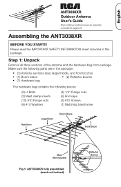
Step 1: Unpack Remove all three sections of the antenna and the hardware bag from package. Make sure the following parts are in this package. English ANT3038XR Outdoor Antenna User's Guide Para obtener instrucciones en español, consulte la página 9. Assembling the ANT3038XR BEFORE YOU START!!! Please read the IMPORTANT SAFETY INFORMATION sheet included in the package: • (3) Antenna sections (rear, large/middle, and front...
Step 1: Unpack Remove all three sections of the antenna and the hardware bag from package. Make sure the following parts are in this package. English ANT3038XR Outdoor Antenna User's Guide Para obtener instrucciones en español, consulte la página 9. Assembling the ANT3038XR BEFORE YOU START!!! Please read the IMPORTANT SAFETY INFORMATION sheet included in the package: • (3) Antenna sections (rear, large/middle, and front...

Owner/User Manual
Page 2
...to each other . (See Fig. 3.) Fig. 3 2 The reflector booms should be unfolded in either direction. Make sure that all the other elements on the antenna until they lock into place ensuring that the front of their locking tabs face towards each other . Fig. 1 Fig. 2 FRONT Locking Tab ...antenna Unfold all of the elements are flat and parallel to the reflector boom. Connect the two reflector booms to the front (small) boom Find the two reflector booms and the front (or small) boom. Step 2: Connect the reflector booms to the front boom using...
...to each other . (See Fig. 3.) Fig. 3 2 The reflector booms should be unfolded in either direction. Make sure that all the other elements on the antenna until they lock into place ensuring that the front of their locking tabs face towards each other . Fig. 1 Fig. 2 FRONT Locking Tab ...antenna Unfold all of the elements are flat and parallel to the reflector boom. Connect the two reflector booms to the front (small) boom Find the two reflector booms and the front (or small) boom. Step 2: Connect the reflector booms to the front boom using...

Owner/User Manual
Page 3
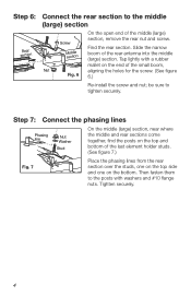
... narrow boom of the middle section that matches figure 4. Step 5: Connect the phasing lines Place the phasing lines from the front section over the studs. Secure them to the studs with a rubber mallet on this same side. English Step 4: Connect the middle (large) section to tighten securely. Phasing Lines Fig.... the screw. (See figure 4.) Re-install the screw and nut; Make sure the Middle section Front section phasing lines are on the top side of the small boom and the black plastic element holders are also on the end of the antenna. (See figure 5.) Fig. 4 Tap...
... narrow boom of the middle section that matches figure 4. Step 5: Connect the phasing lines Place the phasing lines from the front section over the studs. Secure them to the studs with a rubber mallet on this same side. English Step 4: Connect the middle (large) section to tighten securely. Phasing Lines Fig.... the screw. (See figure 4.) Re-install the screw and nut; Make sure the Middle section Front section phasing lines are on the top side of the small boom and the black plastic element holders are also on the end of the antenna. (See figure 5.) Fig. 4 Tap...
Owner/User Manual
Page 4
... element holder studs. (See figure 7.) Fig. 7 Place the phasing lines from the rear section over the studs, one on the top side and one on the top and bottom of the rear antenna into the middle (large) section. Step 6: Rear section Connect the rear section to the middle (large) section On... the open end of the small boom, Nut aligning the holes for the screw. (See figure Fig. 6 6.) Re-install the screw and nut;
... element holder studs. (See figure 7.) Fig. 7 Place the phasing lines from the rear section over the studs, one on the top side and one on the top and bottom of the rear antenna into the middle (large) section. Step 6: Rear section Connect the rear section to the middle (large) section On... the open end of the small boom, Nut aligning the holes for the screw. (See figure Fig. 6 6.) Re-install the screw and nut;

Owner/User Manual
Page 5
Use one of the provided #10 screws and nuts. (See figure 8.) Fig. 9 Screw Swing the boom brace down towards the Nut rear. Fig. 10 Downlead Transformer connections 5 Place the transformer ends between the two washers and tighten the nuts securely. (See figure 10.) Attach the coax downlead... one of the studs. English Step 8: Connect the boom brace Lay the boom brace on top of each of the provided #10 screws and nuts to attach the "V" to the transformer. Make sure the mast clamps (the brass-colored sections) on top of the antenna. Fig. 8 Locate the screw...
Use one of the provided #10 screws and nuts. (See figure 8.) Fig. 9 Screw Swing the boom brace down towards the Nut rear. Fig. 10 Downlead Transformer connections 5 Place the transformer ends between the two washers and tighten the nuts securely. (See figure 10.) Attach the coax downlead... one of the studs. English Step 8: Connect the boom brace Lay the boom brace on top of each of the provided #10 screws and nuts to attach the "V" to the transformer. Make sure the mast clamps (the brass-colored sections) on top of the antenna. Fig. 8 Locate the screw...
Owner/User Manual
Page 6
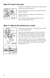
.... Attach the nuts loosely. Step 11: Mount the antenna to gently tap them into the mast clamps and mast clamp inserts. Then insert the U-bolts into the ends so that they are secure. Insert a third plastic end cap in the exposed end of the mast clamps on the antennas as shown in figure...of the antenna is the side with the black plastic pieces on the ends of the reflector booms. Use a rubber mallet to a mast #10 Nuts Boom brace Clamp insert Main boom Clamp insert Fig. 12 Find the two U-bolts, four 1/4" flange nuts, and the two mast clamp inserts. Step 10: Insert...
.... Attach the nuts loosely. Step 11: Mount the antenna to gently tap them into the mast clamps and mast clamp inserts. Then insert the U-bolts into the ends so that they are secure. Insert a third plastic end cap in the exposed end of the mast clamps on the antennas as shown in figure...of the antenna is the side with the black plastic pieces on the ends of the reflector booms. Use a rubber mallet to a mast #10 Nuts Boom brace Clamp insert Main boom Clamp insert Fig. 12 Find the two U-bolts, four 1/4" flange nuts, and the two mast clamp inserts. Step 10: Insert...

Owner/User Manual
Page 7
... TV set while you receive the best picture. Step 13: Secure mast clamps and downlead, ground the antenna Tighten the two mast clamps securely. Ground the antenna and mast per the accompanying grounding instructions. Important: Point The Antenna Toward Your Local Broadcast Towers Visit www.antennaweb.org to see the locations of your TV. English Step 12: Connect the coax downlead to your TV or preamplifier Fig. 14 Point toward broadcast towers Connect the coax downlead...
... TV set while you receive the best picture. Step 13: Secure mast clamps and downlead, ground the antenna Tighten the two mast clamps securely. Ground the antenna and mast per the accompanying grounding instructions. Important: Point The Antenna Toward Your Local Broadcast Towers Visit www.antennaweb.org to see the locations of your TV. English Step 12: Connect the coax downlead to your TV or preamplifier Fig. 14 Point toward broadcast towers Connect the coax downlead...

Owner/User Manual
Page 8
...sale), specification of defect(s), transportation prepaid, to the elimination of externally generated static or noise. THE EXTENT OF THE COMPANY'S LIABILITY UNDER THIS WARRANTY IS LIMITED TO THE REPAIR OR REPLACEMENT PROVIDED ABOVE AND, IN NO EVENT, SHALL THE COMPANY'S LIABILITY EXCEED THE PURCHASE PRICE...has been damaged through acts of nature, alteration, improper installation, mishandling, misuse, neglect, or accident. No person or representative is not transferable and does not cover product purchased, serviced or used outside the United States or Canada. Do not return this ...
...sale), specification of defect(s), transportation prepaid, to the elimination of externally generated static or noise. THE EXTENT OF THE COMPANY'S LIABILITY UNDER THIS WARRANTY IS LIMITED TO THE REPAIR OR REPLACEMENT PROVIDED ABOVE AND, IN NO EVENT, SHALL THE COMPANY'S LIABILITY EXCEED THE PURCHASE PRICE...has been damaged through acts of nature, alteration, improper installation, mishandling, misuse, neglect, or accident. No person or representative is not transferable and does not cover product purchased, serviced or used outside the United States or Canada. Do not return this ...


