
English Manual
Page 1
... Mon.-Fri., 6 a.m.-6 p.m. Serial Number Decal (Under Seat) QUESTIONS? Model No. As a manufacturer, we are committed to providing complete customer satisfaction. Visit our website at www.proform.com new products, prizes, fitness tips, and much more! Save this equipment. Write the serial number in this manual before using this manual for future...
... Mon.-Fri., 6 a.m.-6 p.m. Serial Number Decal (Under Seat) QUESTIONS? Model No. As a manufacturer, we are committed to providing complete customer satisfaction. Visit our website at www.proform.com new products, prizes, fitness tips, and much more! Save this equipment. Write the serial number in this manual before using this manual for future...
English Manual
Page 2
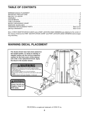
... and a PART LIST/EXPLODED DRAWING are attached in the location shown. Apply the decal in the center of this manual and order a free replacement decal. PROFORM is missing or illegible, please call the toll-free telephone number on the weight system.
... and a PART LIST/EXPLODED DRAWING are attached in the location shown. Apply the decal in the center of this manual and order a free replacement decal. PROFORM is missing or illegible, please call the toll-free telephone number on the weight system.
English Manual
Page 3
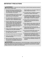
It is the responsibility of the owner to ensure that does not use the weight system. 5. Place the weight system on a level surface, with a mat beneath it to be used only with the lock pin and lock after exercising to mount, dismount, and use the lat bar. 15. Keep children under 12 and pets away from the weight system when performing an exercise that all times. The weight system is designed to support a maximum user weight of all cables at any time while exercising, stop immediately and make sure that there is especially important for home use of the weight system (see ...
It is the responsibility of the owner to ensure that does not use the weight system. 5. Place the weight system on a level surface, with a mat beneath it to be used only with the lock pin and lock after exercising to mount, dismount, and use the lat bar. 15. Keep children under 12 and pets away from the weight system when performing an exercise that all times. The weight system is designed to support a maximum user weight of all cables at any time while exercising, stop immediately and make sure that there is especially important for home use of the weight system (see ...
English Manual
Page 4
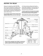
..., build dramatic muscle size and strength, or improve your benefit, read this manual carefully before calling. To avoid a registration fee for selecting the versatile PROFORM® FUSION 6.0 LX weight system. Right Side Butterfly Arm Backrest Left Side High Pulley Station Lat Bar Military Press Arm Adjustable Backrest Curl Pad Seat Leg Lever Low...
..., build dramatic muscle size and strength, or improve your benefit, read this manual carefully before calling. To avoid a registration fee for selecting the versatile PROFORM® FUSION 6.0 LX weight system. Right Side Butterfly Arm Backrest Left Side High Pulley Station Lat Bar Military Press Arm Adjustable Backrest Curl Pad Seat Leg Lever Low...

English Manual
Page 5
Assembly Requires Two Persons For your convenience and safety, assemble the weight system with the help you identify the small parts used . If a part is completed. Tightening Parts How to make assembly as easy as possible, we have included a PART IDENTIFICATION CHART in the center of the packing materials until you begin by almost anyone. Place all Tighten all parts are found in individual bags. Arm Assembly-During this manual. Do not dispose of this manual. By deciding to Unpack the Box To make the task enjoyable, assembly will go smoothly. Make sure that there ...
Assembly Requires Two Persons For your convenience and safety, assemble the weight system with the help you identify the small parts used . If a part is completed. Tightening Parts How to make assembly as easy as possible, we have included a PART IDENTIFICATION CHART in the center of the packing materials until you begin by almost anyone. Place all Tighten all parts are found in individual bags. Arm Assembly-During this manual. Do not dispose of this manual. By deciding to Unpack the Box To make the task enjoyable, assembly will go smoothly. Make sure that there ...

English Manual
Page 6
Place a piece of tape over the bolt heads to the Right and Left Bases (1, 2) with an M10 x 120mm Bolt (97), two M10 Washers (109), and an M10 Nylon Locknut (111). Frame Assembly 1 1. Do not overtighten the Locknut; Do not tighten the Bolts yet. 3 57 109 1 2 57 109 111 111 5 6 Attach the Center Base (5) to hold the Bolts in the box on the previous page. the Foot Plate must be able to the Right Base (1) with four M10 x 70mm Bolts (57), four M10 Washers (109), and two M10 Nylon Locknuts (111). Insert two M10 x 80mm Carriage Bolts (112) up through the Left Base (2)....
Place a piece of tape over the bolt heads to the Right and Left Bases (1, 2) with an M10 x 120mm Bolt (97), two M10 Washers (109), and an M10 Nylon Locknut (111). Frame Assembly 1 1. Do not overtighten the Locknut; Do not tighten the Bolts yet. 3 57 109 1 2 57 109 111 111 5 6 Attach the Center Base (5) to hold the Bolts in the box on the previous page. the Foot Plate must be able to the Right Base (1) with four M10 x 70mm Bolts (57), four M10 Washers (109), and two M10 Nylon Locknuts (111). Insert two M10 x 80mm Carriage Bolts (112) up through the Left Base (2)....

English Manual
Page 7
4. Orient the Center Upright (9) so the 2" Square 4 Inner Cap (51) is in the position shown. Do not tighten the Bolts yet. 51 9 5. Attach the Right Upright (7) to the Right and Left Bases (1, 2) with two M10 x 90mm Bolts (102) and two M10 Nylon Locknuts (111). Attach the Center Upright (9) to the Right Base (1) 5 with four M10 x 70mm Bolts (57), four M10 Washers (109), and two M10 Nylon Locknuts (111). Do not tighten the Locknuts yet. 57 109 111 1 57 109 111 2 7 111 1 102 7
4. Orient the Center Upright (9) so the 2" Square 4 Inner Cap (51) is in the position shown. Do not tighten the Bolts yet. 51 9 5. Attach the Right Upright (7) to the Right and Left Bases (1, 2) with two M10 x 90mm Bolts (102) and two M10 Nylon Locknuts (111). Attach the Center Upright (9) to the Right Base (1) 5 with four M10 x 70mm Bolts (57), four M10 Washers (109), and two M10 Nylon Locknuts (111). Do not tighten the Locknuts yet. 57 109 111 1 57 109 111 2 7 111 1 102 7

English Manual
Page 8
Do not tighten the Locknuts yet. 11 111 111 1 112 10 111 111 1 112 8 111 2 102 8 Attach the Right Seat Upright (11) to the Left Base (2) 8 with two M10 x 90mm Bolts (102) and two M10 Nylon Locknuts (111). Attach the Left Upright (8) to the Right 6 Base (1) with the indicated M10 x 80mm Carriage Bolts (112) and two M10 Nylon Locknuts (111). 8. 6. Attach the Curl Post Upright (10) to the Right 7 Base (1) with the indicated M10 x 80mm Carriage Bolts (112) and two M10 Nylon Locknuts (111). 7.
Do not tighten the Locknuts yet. 11 111 111 1 112 10 111 111 1 112 8 111 2 102 8 Attach the Right Seat Upright (11) to the Left Base (2) 8 with two M10 x 90mm Bolts (102) and two M10 Nylon Locknuts (111). Attach the Left Upright (8) to the Right 6 Base (1) with the indicated M10 x 80mm Carriage Bolts (112) and two M10 Nylon Locknuts (111). 8. 6. Attach the Curl Post Upright (10) to the Right 7 Base (1) with the indicated M10 x 80mm Carriage Bolts (112) and two M10 Nylon Locknuts (111). 7.

English Manual
Page 9
9. Attach the Right Top Frame (3) to the Left Upright (8) with two M10 x 90mm Bolts (102) and two M10 Nylon Locknuts (111). Do not tighten the Bolts yet. Do not tighten the Bolts yet. 57 Attach the Left Top Frame (4) to the Center Upright (9) with two M10 x 65mm Bolts (110) and 3 an M10 Nylon Locknut (111). Attach the Butterfly Frame (24) to the Right Top 12 Frame (3) with two M10 x 70mm Bolts (57), two M10 Washers (109), and an M10 Nylon Locknut (111). Do not tighten the Screws yet. 110 111 7 113 24 9 Attach the Butterfly Frame (24) to the Right Upright (7) with two M10 x...
9. Attach the Right Top Frame (3) to the Left Upright (8) with two M10 x 90mm Bolts (102) and two M10 Nylon Locknuts (111). Do not tighten the Bolts yet. Do not tighten the Bolts yet. 57 Attach the Left Top Frame (4) to the Center Upright (9) with two M10 x 65mm Bolts (110) and 3 an M10 Nylon Locknut (111). Attach the Butterfly Frame (24) to the Right Top 12 Frame (3) with two M10 x 70mm Bolts (57), two M10 Washers (109), and an M10 Nylon Locknut (111). Do not tighten the Screws yet. 110 111 7 113 24 9 Attach the Butterfly Frame (24) to the Right Upright (7) with two M10 x...

English Manual
Page 10
Tighten the M10 x 70mm Bolts (57) used in the same manner. Slide eleven Weights (34), with the pin grooves 14 on the bottom, onto a set of Weight Guides (30). Attach the Weight Guide to the bottom. Insert the Weight Tube into the stack of Weights (34). 109 110 68 5 34 30 75 34 34 Pin Groove 10 Hole 111 66 14. Orient a Weight Guide (30) with the indicated 13 hole closer to the Center Base (5) with the other three Weight Guides (30) to the Center Base (5) in step 3. Orient a Weight Tube (75) as shown. Slide a Weight Bumper (66) onto the Weight ...
Tighten the M10 x 70mm Bolts (57) used in the same manner. Slide eleven Weights (34), with the pin grooves 14 on the bottom, onto a set of Weight Guides (30). Attach the Weight Guide to the bottom. Insert the Weight Tube into the stack of Weights (34). 109 110 68 5 34 30 75 34 34 Pin Groove 10 Hole 111 66 14. Orient a Weight Guide (30) with the indicated 13 hole closer to the Center Base (5) with the other three Weight Guides (30) to the Center Base (5) in step 3. Orient a Weight Tube (75) as shown. Slide a Weight Bumper (66) onto the Weight ...

English Manual
Page 11
Attach the other three Weight Guides (30) to a 3" Bushing (71) and the two 17 Large Round Bushings (61) in the same manner. Apply grease to the Butterfly Frame (24) with an M10 x 100mm Bolt (85) and an M10 Nylon Locknut (111). 85 61 Grease Repeat this step with an M10 x 70mm Bolt (57) and an M10 Nylon Locknut (111). 111 15 63 Grease 10 57 17. Apply grease to the Center Top Frame (6) in the Right Butterfly Arm (23). Attach the Butterfly Arm and 3" Bushing to 2" Bushing (63). 15. Do not tighten the Bolts yet. Tighten the bolts, screws and locknuts used in steps 4, 5, 8,...
Attach the other three Weight Guides (30) to a 3" Bushing (71) and the two 17 Large Round Bushings (61) in the same manner. Apply grease to the Butterfly Frame (24) with an M10 x 100mm Bolt (85) and an M10 Nylon Locknut (111). 85 61 Grease Repeat this step with an M10 x 70mm Bolt (57) and an M10 Nylon Locknut (111). 111 15 63 Grease 10 57 17. Apply grease to the Center Top Frame (6) in the Right Butterfly Arm (23). Attach the Butterfly Arm and 3" Bushing to 2" Bushing (63). 15. Do not tighten the Bolts yet. Tighten the bolts, screws and locknuts used in steps 4, 5, 8,...

English Manual
Page 12
Apply grease to the 1 3/4" Bushing (64). Do not overtighten the Locknut; Apply grease to an M10 x 45mm Bolt (95). the Military Press Arm must be able to the Press Frame (13) in the same manner. 13 111 2 102 65 Grease 25 57 26 12 111 13 Attach the Left Press Arm (25) to pivot easily. 104 64 111 Grease 20 Hole 8 Grease 20 111 21 95 20. Attach the Right Press Arm (26) to the Military Press Frame (20) with an M10 x 90mm Bolt (102) and an M10 Nylon Locknut (111). 21. Attach 18 the Military Press Frame (20) and the 1 3/4" Bushing inside the Left Upright (8) ...
Apply grease to the 1 3/4" Bushing (64). Do not overtighten the Locknut; Apply grease to an M10 x 45mm Bolt (95). the Military Press Arm must be able to the Press Frame (13) in the same manner. 13 111 2 102 65 Grease 25 57 26 12 111 13 Attach the Left Press Arm (25) to pivot easily. 104 64 111 Grease 20 Hole 8 Grease 20 111 21 95 20. Attach the Right Press Arm (26) to the Military Press Frame (20) with an M10 x 90mm Bolt (102) and an M10 Nylon Locknut (111). 21. Attach 18 the Military Press Frame (20) and the 1 3/4" Bushing inside the Left Upright (8) ...

English Manual
Page 13
22. Orient the 23 Leg Press (12) with the other Press Arm Handle (27) and the Right Press Arm (26). 23. Repeat this step with the welded spacer on pages 27 and 28 to pivot easily. Apply grease to pivot easily. 111 57 27 Grease 25 27 26 12 2 111 Welded Spacer 108 65 Grease 111 96 Grease 12 29 Cable Assembly 25 92 25. Do not overtighten the Locknut; the Leg Press Plate must be able to an M10 x 75mm Bolt (96). Make sure that the Cable end can pivot easily around the shoulder of the Bolt. 13 Apply grease to an M10 x 70mm Bolt (57). Attach 24 the ...
22. Orient the 23 Leg Press (12) with the other Press Arm Handle (27) and the Right Press Arm (26). 23. Repeat this step with the welded spacer on pages 27 and 28 to pivot easily. Apply grease to pivot easily. 111 57 27 Grease 25 27 26 12 2 111 Welded Spacer 108 65 Grease 111 96 Grease 12 29 Cable Assembly 25 92 25. Do not overtighten the Locknut; the Leg Press Plate must be able to an M10 x 75mm Bolt (96). Make sure that the Cable end can pivot easily around the shoulder of the Bolt. 13 Apply grease to an M10 x 70mm Bolt (57). Attach 24 the ...

English Manual
Page 14
Attach the Pulley, a Cable Trap (48), an M10 Washer (109), and two Half Finger Guards (46) to the Right Upright (7) with an M10 x 50mm Bolt (106) and an M10 Nylon Locknut (111). Attach the Pulley, a Cable Trap (48), an M10 Washer (109), and two Finger Guards (45) to hold the Cable in the groove of the Pulley. 109 97 111 48 45 43 73 109 45 23 29. Make sure that the Cable Trap is oriented to the Right Butterfly Arm (23) with an M10 x 120mm Bolt (97), an M10 Washer (109), and an M10 Nylon Locknut (111). Make sure that the Cable Trap is oriented to identify the ...
Attach the Pulley, a Cable Trap (48), an M10 Washer (109), and two Half Finger Guards (46) to the Right Upright (7) with an M10 x 50mm Bolt (106) and an M10 Nylon Locknut (111). Attach the Pulley, a Cable Trap (48), an M10 Washer (109), and two Finger Guards (45) to hold the Cable in the groove of the Pulley. 109 97 111 48 45 43 73 109 45 23 29. Make sure that the Cable Trap is oriented to the Right Butterfly Arm (23) with an M10 x 120mm Bolt (97), an M10 Washer (109), and an M10 Nylon Locknut (111). Make sure that the Cable Trap is oriented to identify the ...

English Manual
Page 15
Wrap the Butterfly Cable (73) over a Pulley (43). 30 Attach the Pulley to hold the Cable in the groove of Pulley Plates (49) with an M10 x 45mm Bolt (95) and an M10 Nylon Locknut (111). 111 73 43 46 46 49 48 49 106 3 95 111 43 73 33. Repeat this step with an M10 x 40mm Bolt (116) and an M10 Nylon Locknut (111). ed to the Right Top Frame (3) with another Pulley (43). 111 43 73 3 43 116 31. Wrap the Butterfly Cable (73) over a Pulley (43). 33 Attach the Pulley to the Right Top Frame (3) with an M10 x 50mm Bolt (106) and an M10 Nylon Locknut (111). Makes ...
Wrap the Butterfly Cable (73) over a Pulley (43). 30 Attach the Pulley to hold the Cable in the groove of Pulley Plates (49) with an M10 x 45mm Bolt (95) and an M10 Nylon Locknut (111). 111 73 43 46 46 49 48 49 106 3 95 111 43 73 33. Repeat this step with an M10 x 40mm Bolt (116) and an M10 Nylon Locknut (111). ed to the Right Top Frame (3) with another Pulley (43). 111 43 73 3 43 116 31. Wrap the Butterfly Cable (73) over a Pulley (43). 33 Attach the Pulley to the Right Top Frame (3) with an M10 x 50mm Bolt (106) and an M10 Nylon Locknut (111). Makes ...

English Manual
Page 16
Attach the Butterfly Cable (73) and a Weight Cap 34 (67) to the Right Base (1) with an M10 x 50mm Bolt (106) and an M10 Nylon Locknut (111). 73 111 67 106 75 35. 34. Attach a Pulley (43) inside the Curl Post Upright 36 (10), over the Low Cable (70), with an M10 x 65mm Bolt (110), two M10 Washers (109), two 1/2" Spacers (68), and an M10 Nylon Locknut (111). 15 10 111 43 70 95 111 68 109 10 43 70 109 110 68 37. Attach the Pulley, an M10 Washer (109), and two Half Finger Guards (46) to the indicated Weight Tube (75) with an M10 x 45mm Bolt (95) and an M10 Nylon Locknut ...
Attach the Butterfly Cable (73) and a Weight Cap 34 (67) to the Right Base (1) with an M10 x 50mm Bolt (106) and an M10 Nylon Locknut (111). 73 111 67 106 75 35. 34. Attach a Pulley (43) inside the Curl Post Upright 36 (10), over the Low Cable (70), with an M10 x 65mm Bolt (110), two M10 Washers (109), two 1/2" Spacers (68), and an M10 Nylon Locknut (111). 15 10 111 43 70 95 111 68 109 10 43 70 109 110 68 37. Attach the Pulley, an M10 Washer (109), and two Half Finger Guards (46) to the indicated Weight Tube (75) with an M10 x 45mm Bolt (95) and an M10 Nylon Locknut ...

English Manual
Page 17
Attach the Pulley inside the Right Base 39 (1) with an M10 x 65mm Bolt (110), two M10 Washers (109), and an M10 Nylon Locknut (111). 111 49 46 46 48 106 43 70 111 70 109 40. Wrap the Low Cable (70) over a Pulley (43). 38 Attach the Pulley, a Cable Trap (48), and two Half Finger Guards (46) at the second hole from the top of Pulley Plates (49) with an M10 x 50mm Bolt (106) and an M10 Nylon Locknut (111). Wrap the High Cable (88) under a Pulley (43). 42 Attach the Pulley, a Cable Trap (48), an M10 Washer (109), and two Half Finger Guards (46) at the bottom hole of ...
Attach the Pulley inside the Right Base 39 (1) with an M10 x 65mm Bolt (110), two M10 Washers (109), and an M10 Nylon Locknut (111). 111 49 46 46 48 106 43 70 111 70 109 40. Wrap the Low Cable (70) over a Pulley (43). 38 Attach the Pulley, a Cable Trap (48), and two Half Finger Guards (46) at the second hole from the top of Pulley Plates (49) with an M10 x 50mm Bolt (106) and an M10 Nylon Locknut (111). Wrap the High Cable (88) under a Pulley (43). 42 Attach the Pulley, a Cable Trap (48), an M10 Washer (109), and two Half Finger Guards (46) at the bottom hole of ...

English Manual
Page 18
43. Wrap the High Cable (88) over a Pulley (43). 47 Attach the Pulley to the Left Top Frame (4) with an M10 x 45mm Bolt (95) and an M10 Nylon Locknut (111). 46 111 109 88 46 43 95 20 4 111 95 88 43 47. Attach the Pulley inside the Top Frame with an M10 x 65mm Bolt (110), two M10 Washers (109), two 1/2" Spacers (68), and an M10 Nylon Locknut (111). 43 109 68 110 84 88 111 109 68 4 44. Wrap the High Cable (88) over a Small Pulley (84). Route the High Cable (88) over a Small Pulley 44 (84) and down through the Left Top Frame (4) and over a Pulley (43). 46 ...
43. Wrap the High Cable (88) over a Pulley (43). 47 Attach the Pulley to the Left Top Frame (4) with an M10 x 45mm Bolt (95) and an M10 Nylon Locknut (111). 46 111 109 88 46 43 95 20 4 111 95 88 43 47. Attach the Pulley inside the Top Frame with an M10 x 65mm Bolt (110), two M10 Washers (109), two 1/2" Spacers (68), and an M10 Nylon Locknut (111). 43 109 68 110 84 88 111 109 68 4 44. Wrap the High Cable (88) over a Small Pulley (84). Route the High Cable (88) over a Small Pulley 44 (84) and down through the Left Top Frame (4) and over a Pulley (43). 46 ...

English Manual
Page 19
Attach the Cable to hold the Cable in the groove of the Pulley. 109 46 95 111 48 46 43 72 13 19 Make sure that the Cable Trap is oriented to 49 the Left Base (2) with an M10 x 120mm Bolt (97) and an M10 Nylon Locknut (111). Make sure that the Cable Trap is oriented to hold the Cable in the groove of the Bolt. 88 111 67 106 75 92 2 72 50. Make sure that the Cable Trap is oriented to hold the Cable in the groove of the Pulley. 51. Wrap the Press Cable (72) under a Pulley (43). 52 Attach the Pulley, a Cable Trap (48), an M10 Washer (109), and two Half ...
Attach the Cable to hold the Cable in the groove of the Pulley. 109 46 95 111 48 46 43 72 13 19 Make sure that the Cable Trap is oriented to 49 the Left Base (2) with an M10 x 120mm Bolt (97) and an M10 Nylon Locknut (111). Make sure that the Cable Trap is oriented to hold the Cable in the groove of the Bolt. 88 111 67 106 75 92 2 72 50. Make sure that the Cable Trap is oriented to hold the Cable in the groove of the Pulley. 51. Wrap the Press Cable (72) under a Pulley (43). 52 Attach the Pulley, a Cable Trap (48), an M10 Washer (109), and two Half ...

English Manual
Page 20
Make sure that only two threads of the Pulley. 46 48 109 111 107 43 46 72 2 54. 53. it should be tightened so that the Cable Trap is oriented to hold the Cable in the groove of the Cable show past the Locknut. 103 114 50 72 Seat Assembly 55 55. Attach a Backrest (35) and a Backrest Plate (117) 56 to the Small Pulley 54 Plate (50) with four M6 x 30mm Screws (99). 35 20 99 99 99 7 Attach the Press Cable (72) to the Right Upright (7) with an M6 Washer (114) and an M6 Nylon Locknut (103). Attach the Curl Pad (38) and the Curl Plate (120) to the Left Base ...
Make sure that only two threads of the Pulley. 46 48 109 111 107 43 46 72 2 54. 53. it should be tightened so that the Cable Trap is oriented to hold the Cable in the groove of the Cable show past the Locknut. 103 114 50 72 Seat Assembly 55 55. Attach a Backrest (35) and a Backrest Plate (117) 56 to the Small Pulley 54 Plate (50) with four M6 x 30mm Screws (99). 35 20 99 99 99 7 Attach the Press Cable (72) to the Right Upright (7) with an M6 Washer (114) and an M6 Nylon Locknut (103). Attach the Curl Pad (38) and the Curl Plate (120) to the Left Base ...