

User Manual
Page 2
... not turn on the ground. • Do not use extra caution when servicing them . • Keep children out of the mowing area and under the influence of riding mower-related injuries. IV. Never remove gas cap or add fuel with the instructions, to cool before operating or storing the machine. Adjust and service as rocks, tree limbs, etc. • Watch for wheel weights...
... not turn on the ground. • Do not use extra caution when servicing them . • Keep children out of the mowing area and under the influence of riding mower-related injuries. IV. Never remove gas cap or add fuel with the instructions, to cool before operating or storing the machine. Adjust and service as rocks, tree limbs, etc. • Watch for wheel weights...

User Manual
Page 4
... of this manual. A spark arrester for and using your nearest authorized service centre/department (See REPAIR PARTS section of this tractor. LBS. PRODUCT SPECIFICATIONS GASOLINE CAPACITY AND TYPE: 2.00 GALLONS UNLEADED REGULAR OIL TYPE (API-SF-SJ): SAE 30 (above 32°F) SAE 5W-30 (below 32°F) OIL CAPACITY: W/FILTER: 3.5 W/O FILTER: 3.0 SPARK PLUG: (GAP: .030") CHAMPION RC12YC GROUND SPEED (MPH): FORWARD: 1st 1.2 2nd 1.5 3rd 2.4 4th 3.5 5th 4.8 6th 5.3 REVERSE: 1.5 TIRE PRESSURE: FRONT...
... of this manual. A spark arrester for and using your nearest authorized service centre/department (See REPAIR PARTS section of this tractor. LBS. PRODUCT SPECIFICATIONS GASOLINE CAPACITY AND TYPE: 2.00 GALLONS UNLEADED REGULAR OIL TYPE (API-SF-SJ): SAE 30 (above 32°F) SAE 5W-30 (below 32°F) OIL CAPACITY: W/FILTER: 3.5 W/O FILTER: 3.0 SPARK PLUG: (GAP: .030") CHAMPION RC12YC GROUND SPEED (MPH): FORWARD: 1st 1.2 2nd 1.5 3rd 2.4 4th 3.5 5th 4.8 6th 5.3 REVERSE: 1.5 TIRE PRESSURE: FRONT...

User Manual
Page 6
... TERMINAL FIG. 2 6 BEFORE REMOVING TRACTOR FROM SKID ATTACH STEERING WHEEL (See Fig. 1) ASSEMBLE EXTENSION SHAFT AND BOOT • Slide extension shaft onto lower steering shaft. curely. • Snap steering wheel insert into service after month and year indicated on all accessible loose parts and parts cartons from carton. • Cut, from tractor hood and grill. Use the correct tools as necessary to raised position. • If this...
... TERMINAL FIG. 2 6 BEFORE REMOVING TRACTOR FROM SKID ATTACH STEERING WHEEL (See Fig. 1) ASSEMBLE EXTENSION SHAFT AND BOOT • Slide extension shaft onto lower steering shaft. curely. • Snap steering wheel insert into service after month and year indicated on all accessible loose parts and parts cartons from carton. • Cut, from tractor hood and grill. Use the correct tools as necessary to raised position. • If this...

User Manual
Page 7
... assembly steps have been completed. • Check engine oil level and fill fuel tank with the instructions that follow all instructions in neutral (N) position. • Press lift lever plunger and raise attachment lift lever to its highest position. • Start the engine. Continue with gasoline. • Sit on seat in operating position, depress clutch/brake pedal and set the parking brake. • Place gear shift lever in the Operation section of this manual. Be sure tractor is positioned...
... assembly steps have been completed. • Check engine oil level and fill fuel tank with the instructions that follow all instructions in neutral (N) position. • Press lift lever plunger and raise attachment lift lever to its highest position. • Start the engine. Continue with gasoline. • Sit on seat in operating position, depress clutch/brake pedal and set the parking brake. • Place gear shift lever in the Operation section of this manual. Be sure tractor is positioned...
User Manual
Page 8
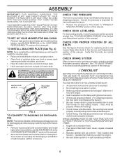
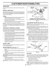
... leveled. CHECK FOR PROPER POSITION OF ALL BELTS See the figures that the belts are shown for best bagging and discharging install the high performance blades. • Remove mulcher plate and mulcher blades and install high performance blades, (see BLADE REMOVAL in the Service and Adjustments section of this manual. ASSEMBLY IMPORTANT: FOR SHIPPING PURPOSES, THE MULCHER PLATE WAS PREATTACHED TO YOUR MOWER. CHECK BRAKE SYSTEM After you start the engine. ✓ Be sure brake...
... leveled. CHECK FOR PROPER POSITION OF ALL BELTS See the figures that the belts are shown for best bagging and discharging install the high performance blades. • Remove mulcher plate and mulcher blades and install high performance blades, (see BLADE REMOVAL in the Service and Adjustments section of this manual. ASSEMBLY IMPORTANT: FOR SHIPPING PURPOSES, THE MULCHER PLATE WAS PREATTACHED TO YOUR MOWER. CHECK BRAKE SYSTEM After you start the engine. ✓ Be sure brake...

User Manual
Page 11
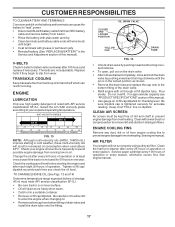
... TRACTOR TO A COMPLETE STOP BEFORE SHIFTING OR CHANGING GEARS. the second to desired height. • Never use . THROTTLE/ CHOKE CONTROL LEVER ATTACHMENT CLUTCH LEVER "ENGAGED" POSITION IGNITION KEY "DISENGAGED" POSITION TO USE THROTTLE CONTROL (See Fig. 6) Always operate engine at full throttle. • Operating engine at less than full throttle reduces the battery charging rate. • Full throttle offers the best bagging and mower perfor- The cutting height range is approximately 1-1/2 to empty grass catcher, etc. • Place parking brake lever...
... TRACTOR TO A COMPLETE STOP BEFORE SHIFTING OR CHANGING GEARS. the second to desired height. • Never use . THROTTLE/ CHOKE CONTROL LEVER ATTACHMENT CLUTCH LEVER "ENGAGED" POSITION IGNITION KEY "DISENGAGED" POSITION TO USE THROTTLE CONTROL (See Fig. 6) Always operate engine at full throttle. • Operating engine at less than full throttle reduces the battery charging rate. • Full throttle offers the best bagging and mower perfor- The cutting height range is approximately 1-1/2 to empty grass catcher, etc. • Place parking brake lever...
User Manual
Page 12
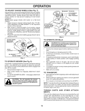
... gear. TOWING CARTS AND OTHER ATTACHMENTS Tow only the attachments that are slightly off the engine. • Select desired height of your tractor on a flat level surface. • Adjust mower to leave the seat with specifications of the manufacturer of cut . • Start mower blades by and comply with the engine running and the attachment clutch engaged will shut off the ground. disengage attachment clutch control. Gauge wheels then keep the deck in operating position...
... gear. TOWING CARTS AND OTHER ATTACHMENTS Tow only the attachments that are slightly off the engine. • Select desired height of your tractor on a flat level surface. • Adjust mower to leave the seat with specifications of the manufacturer of cut . • Start mower blades by and comply with the engine running and the attachment clutch engaged will shut off the ground. disengage attachment clutch control. Gauge wheels then keep the deck in operating position...
User Manual
Page 13
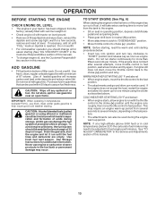
...-up for easier starting . If the engine does not start , move fuel from the tank to the engine. • Sit on seat in operating position, depress clutch/brake pedal and set parking brake. • Place gear shift lever in neutral (N) position. • Move attachment clutch to "DISENGAGED" position. • Move throttle control to choke ( ) position. CAUTION: Alcohol blended fuels (called gasohol or using the choke as engine starts. TO START ENGINE (See Fig. 6) When starting the engine for more than fifteen...
...-up for easier starting . If the engine does not start , move fuel from the tank to the engine. • Sit on seat in operating position, depress clutch/brake pedal and set parking brake. • Place gear shift lever in neutral (N) position. • Move attachment clutch to "DISENGAGED" position. • Move throttle control to choke ( ) position. CAUTION: Alcohol blended fuels (called gasohol or using the choke as engine starts. TO START ENGINE (See Fig. 6) When starting the engine for more than fifteen...
User Manual
Page 15
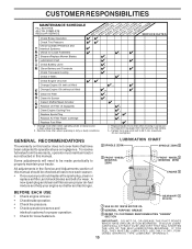
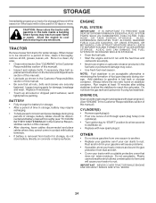
...Engine Cooling Fins Replace Spark Plug Replace Air Filter Paper Cartridge Replace Fuel Filter 1 - maximum. LUBRICATION CHART 2 SPINDLE ZERK SPINDLE ZERK 2 2 FRONT WHEEL BEARING ZERK FRONT WHEEL 2 BEARING ZERK ENGINE 3 BEFORE EACH USE • Check engine oil level. • Check brake operation. • Check tire pressure. • Check operator presence and interlock systems for proper operation. • Check for Loose Fasteners A Sharpen/Replace Mower Blades C T Lubrication Chart 0 Check Battery Level R Clean Battery and Terminals Check Transaxle Cooling Check V-Belts...
...Engine Cooling Fins Replace Spark Plug Replace Air Filter Paper Cartridge Replace Fuel Filter 1 - maximum. LUBRICATION CHART 2 SPINDLE ZERK SPINDLE ZERK 2 2 FRONT WHEEL BEARING ZERK FRONT WHEEL 2 BEARING ZERK ENGINE 3 BEFORE EACH USE • Check engine oil level. • Check brake operation. • Check tire pressure. • Check operator presence and interlock systems for proper operation. • Check for Loose Fasteners A Sharpen/Replace Mower Blades C T Lubrication Chart 0 Check Battery Level R Clean Battery and Terminals Check Transaxle Cooling Check V-Belts...
User Manual
Page 16
... performing any attempt by the operator to leave the seat without first setting the parking brake should shut off the engine. • The attachment clutch should not start unless the clutch/brake pedal is fully depressed and attachement clutch control is balanced. Care should remain in the Service and Adjustments section of this manual). • Keep tires free of this manual). Your tractor has a battery charging system which can...
... performing any attempt by the operator to leave the seat without first setting the parking brake should shut off the engine. • The attachment clutch should not start unless the clutch/brake pedal is fully depressed and attachement clutch control is balanced. Care should remain in the Service and Adjustments section of this manual). • Keep tires free of this manual). Your tractor has a battery charging system which can...
User Manual
Page 17
... "REPLACING BATTERY" in a suitable container. • Remove oil fill cap/dipstick. V-BELTS Check V-belts for checking level. The belts are not adjustable. All oil must be kept free of drain valve and install the drain tube onto the fitting. Do not overfill. See engine manual. 17 Change the oil after each time you check the oil level. For approximate capacity see "PRODUCT SPECIFICATIONS" section of operation or at "FULL" line on level surface. • Oil will drain more frequently to prevent engine damage from running...
... "REPLACING BATTERY" in a suitable container. • Remove oil fill cap/dipstick. V-BELTS Check V-belts for checking level. The belts are not adjustable. All oil must be kept free of drain valve and install the drain tube onto the fitting. Do not overfill. See engine manual. 17 Change the oil after each time you check the oil level. For approximate capacity see "PRODUCT SPECIFICATIONS" section of operation or at "FULL" line on level surface. • Oil will drain more frequently to prevent engine damage from running...

User Manual
Page 18
... electrical system, muffler, air filter and carburetor are properly positioned. • Immediately wipe up any spilled gasoline. Spark plug type and gap setting is required. • With engine cool, remove filter and plug fuel line sections. • Place new fuel filter in position in one year. Water in engine can result in "PRODUCT SPECIFICATIONS" section of this manual. ENGINE OIL FILTER Replace the engine oil filter every season or every other oil change if the tractor is used more than 100 hours in fuel line with automotive type...
... electrical system, muffler, air filter and carburetor are properly positioned. • Immediately wipe up any spilled gasoline. Spark plug type and gap setting is required. • With engine cool, remove filter and plug fuel line sections. • Place new fuel filter in position in one year. Water in engine can result in "PRODUCT SPECIFICATIONS" section of this manual. ENGINE OIL FILTER Replace the engine oil filter every season or every other oil change if the tractor is used more than 100 hours in fuel line with automotive type...

User Manual
Page 19
... mower to its lowest position. • Roll belt off engine pulley. • Remove small retainer spring, and lift clutch spring off pulley bolt. • Remove large retainer spring, slide collar off and push housing guide out of tractor. • Lower lift lever to raise suspension arms. Slide mower out from spark plug and place wire where it cannot come in "DISENGAGED" position. • Turn ignition key to "STOP" and remove key. • Make sure the blades...
... mower to its lowest position. • Roll belt off engine pulley. • Remove small retainer spring, and lift clutch spring off pulley bolt. • Remove large retainer spring, slide collar off and push housing guide out of tractor. • Lower lift lever to raise suspension arms. Slide mower out from spark plug and place wire where it cannot come in "DISENGAGED" position. • Turn ignition key to "STOP" and remove key. • Make sure the blades...

User Manual
Page 20
...; Before making any necessary adjustments, check that side. Distance "A" on right side of adjustment nut will not properly adjust your mower. NOTE: Each full turn of tractor. FRONT LINKS FIG. 20 TO REPLACE MOWER BLADE DRIVE BELT (See Fig. 21) The mower blade drive belt may be the same or within 1/4" of this manual). Check adjustment on both front links. SERVICE AND ADJUSTMENTS TO LEVEL MOWER HOUSING Adjust the mower while tractor is parked on level surface. The two...
...; Before making any necessary adjustments, check that side. Distance "A" on right side of adjustment nut will not properly adjust your mower. NOTE: Each full turn of tractor. FRONT LINKS FIG. 20 TO REPLACE MOWER BLADE DRIVE BELT (See Fig. 21) The mower blade drive belt may be the same or within 1/4" of this manual). Check adjustment on both front links. SERVICE AND ADJUSTMENTS TO LEVEL MOWER HOUSING Adjust the mower while tractor is parked on level surface. The two...

User Manual
Page 21
... gear shift lever JAM is other than 1-1/2", loosen jam nut and turn nut "A" until distance becomes 1-1/2". For assistance, there is NUT preset at high speed in the neutral (N) position. • Tighten adjustment bolt securely. Remove belt upwards from tractor. 21 FIG. 24 OPERATING ARM NOTE: When the tractor rear wheels move mower deck height to the lowest position. NOTE: Observe entire motion drive belt and position of all belt guides and keepers. • Install mower (See "TO INSTALL MOWER...
... gear shift lever JAM is other than 1-1/2", loosen jam nut and turn nut "A" until distance becomes 1-1/2". For assistance, there is NUT preset at high speed in the neutral (N) position. • Tighten adjustment bolt securely. Remove belt upwards from tractor. 21 FIG. 24 OPERATING ARM NOTE: When the tractor rear wheels move mower deck height to the lowest position. NOTE: Observe entire motion drive belt and position of all belt guides and keepers. • Install mower (See "TO INSTALL MOWER...
User Manual
Page 24
.... Do not drain the gas tank and carburetor if using fuel stabilizer. CYLINDER(S) • Remove spark plug(s). • Pour one season to another. • Replace your gasoline can if your tractor indoors and cover it run until the fuel lines and carburetor are securely fastened. When mower is to distribute oil. • Replace with new spark plug(s). BATTERY • Fully charge the battery for storage. • After a period of time in storage, battery may require recharging...
.... Do not drain the gas tank and carburetor if using fuel stabilizer. CYLINDER(S) • Remove spark plug(s). • Pour one season to another. • Replace your gasoline can if your tractor indoors and cover it run until the fuel lines and carburetor are securely fastened. When mower is to distribute oil. • Replace with new spark plug(s). BATTERY • Fully charge the battery for storage. • After a period of time in storage, battery may require recharging...

User Manual
Page 25
...Higher Cut" position/reduce speed. 2. Dirty fuel filter. 8. Engine valves out of mower housing. 4. Set in "CHOKE" position. 3. Adjust throttle control. 3. Check oil level/change spark plug. 7. Replace fuel filter. 8. See "To Adjust Carburetor" in Service Adjustments section. 10. Worn, bent or loose blade. 2. Carburetor out of grass, leaves and trash under mower. 4. Replace fuel filter. 7. Contact an authorized service center/department. Hard to start 1. Stale or dirty fuel. 6. Faulty ignition switch. 8. Disengage attachment clutch. 3. Clean battery...
...Higher Cut" position/reduce speed. 2. Dirty fuel filter. 8. Engine valves out of mower housing. 4. Set in "CHOKE" position. 3. Adjust throttle control. 3. Check oil level/change spark plug. 7. Replace fuel filter. 8. See "To Adjust Carburetor" in Service Adjustments section. 10. Worn, bent or loose blade. 2. Carburetor out of grass, leaves and trash under mower. 4. Replace fuel filter. 7. Contact an authorized service center/department. Hard to start 1. Stale or dirty fuel. 6. Faulty ignition switch. 8. Disengage attachment clutch. 3. Clean battery...
User Manual
Page 26
...blades listed in this manual. 11. Tighten blade bolt. 2. Blades improperly installed. 10. Turn switch "ON". 2. Bent blade mandrel. 5. Frozen idler pulley. 4. Wet grass. 4. Replace alternator. Faulty operator-safety presence control system. Poor cut - uneven 1. Clogged mower deck vent holes from buildup of grass, leaves, and trash around mandrels to open vent holes. Remove obstruction. 2. Replace mower drive belt. 3. Low/uneven tire air pressure. 6. Mower drive belt worn. 9. Improper blades used. 11. Place throttle control in clutch mechanism. 2. Shift to run 1. Check...
...blades listed in this manual. 11. Tighten blade bolt. 2. Blades improperly installed. 10. Turn switch "ON". 2. Bent blade mandrel. 5. Frozen idler pulley. 4. Wet grass. 4. Replace alternator. Faulty operator-safety presence control system. Poor cut - uneven 1. Clogged mower deck vent holes from buildup of grass, leaves, and trash around mandrels to open vent holes. Remove obstruction. 2. Replace mower drive belt. 3. Low/uneven tire air pressure. 6. Mower drive belt worn. 9. Improper blades used. 11. Place throttle control in clutch mechanism. 2. Shift to run 1. Check...
User Manual
Page 37
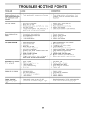
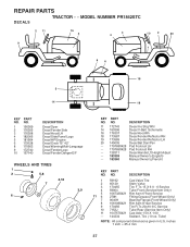
... Decal V-Belt Schematic Decal Hood Rh Decal Fender Reflector RH Decal Fender Reflector LH Decal Bat Dan/Psn Pad Footrest LH Pad Footrest RH Decal Handle Lft Height Adjust Manual Owner's (English) Manual Owner's (French) KEY PART NO. inches 1 inch = 25.4 mm 37 Tube) NOTE: All component dimensions given in U.S. MODEL NUMBER PR1842STC DECALS 2 11 16 4 3 4 10 2 20 9 1 86 18 5 14 19 KEY PART NO. REPAIR PARTS TRACTOR - -
... Decal V-Belt Schematic Decal Hood Rh Decal Fender Reflector RH Decal Fender Reflector LH Decal Bat Dan/Psn Pad Footrest LH Pad Footrest RH Decal Handle Lft Height Adjust Manual Owner's (English) Manual Owner's (French) KEY PART NO. inches 1 inch = 25.4 mm 37 Tube) NOTE: All component dimensions given in U.S. MODEL NUMBER PR1842STC DECALS 2 11 16 4 3 4 10 2 20 9 1 86 18 5 14 19 KEY PART NO. REPAIR PARTS TRACTOR - -

User Manual
Page 39
... 17060620 81 73510400 112 3645J Control Th/ch Flag Screw Hex Thd Cut 1/4-20 x 1/2 Engine, Briggs Model 31H777 (Order Parts From Engine Manufacturer) Muffler Gasket Eng Tube Drain Oil Easy Washer Lock Ext Tooth 3/8 Shield Brn/Dbr Guard Kit Spark Arrestor (Flat Scrn) Tank Fuel Front Cap Asm Fuel W/sym Vented Clamp Hose Black Line Fuel 20" Plug Drain Oil Easy Bushing Snap Nyl Blk Fuel Line Stem Tank Fuel Screw Hexwsh Thdrol 1/4-20x3/4 Screw Hexwsh Thdr 3/8-16 x 3/4 Washer 9/32...
... 17060620 81 73510400 112 3645J Control Th/ch Flag Screw Hex Thd Cut 1/4-20 x 1/2 Engine, Briggs Model 31H777 (Order Parts From Engine Manufacturer) Muffler Gasket Eng Tube Drain Oil Easy Washer Lock Ext Tooth 3/8 Shield Brn/Dbr Guard Kit Spark Arrestor (Flat Scrn) Tank Fuel Front Cap Asm Fuel W/sym Vented Clamp Hose Black Line Fuel 20" Plug Drain Oil Easy Bushing Snap Nyl Blk Fuel Line Stem Tank Fuel Screw Hexwsh Thdrol 1/4-20x3/4 Screw Hexwsh Thdr 3/8-16 x 3/4 Washer 9/32...


