User Manual
Page 4
... of procedures other than those specified herein may result in the installation, use, servicing and maintenance of this equipment from the type of power source indicated on any injuries, the following safety precautions should be observed in hazardous radiation exposure. The equipment may cause the equipment and cart/stand...
... of procedures other than those specified herein may result in the installation, use, servicing and maintenance of this equipment from the type of power source indicated on any injuries, the following safety precautions should be observed in hazardous radiation exposure. The equipment may cause the equipment and cart/stand...

User Manual
Page 5
... damage to support the weight of your warranty. The equipment may cause poor ventilation. ▪ Unplug this equipment near any heat sources such as power-supply cord or plug is sturdy, level, stable and strong enough to the equipment itself. too close to drapes/curtains/walls, in a bookcase,... storms or when unused for a long period of time. ▪ Refer all servicing to fire or electric shock. ▪ Protect the power cord from being walked on or pinchrd particularly at plugs ,convenience receptacles, and the point where they exit from the apparatus. ▪ Do not ...
... damage to support the weight of your warranty. The equipment may cause poor ventilation. ▪ Unplug this equipment near any heat sources such as power-supply cord or plug is sturdy, level, stable and strong enough to the equipment itself. too close to drapes/curtains/walls, in a bookcase,... storms or when unused for a long period of time. ▪ Refer all servicing to fire or electric shock. ▪ Protect the power cord from being walked on or pinchrd particularly at plugs ,convenience receptacles, and the point where they exit from the apparatus. ▪ Do not ...
User Manual
Page 6
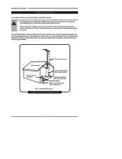
...▪ An outdoor antenna should not be located in any area where it could come in contact with overhead power lines, or any other electric light or power circuits. ▪ When installing an outdoor antenna system, extreme caution should be taken to grounding electrodes, and ...lead-in wire Ground clamps Electric service equipment Antenna discharge unit (NEC section 810-20) Grounding conductors (NEC section 810-20) Ground clamps Power service grounding (NEC Art250 part H) NEC : National Electrical code EXAMPLE OF OUTDOOR ANTENNA GROUNDING 4 Antenna lead-in wire to an antenna...
...▪ An outdoor antenna should not be located in any area where it could come in contact with overhead power lines, or any other electric light or power circuits. ▪ When installing an outdoor antenna system, extreme caution should be taken to grounding electrodes, and ...lead-in wire Ground clamps Electric service equipment Antenna discharge unit (NEC section 810-20) Grounding conductors (NEC section 810-20) Ground clamps Power service grounding (NEC Art250 part H) NEC : National Electrical code EXAMPLE OF OUTDOOR ANTENNA GROUNDING 4 Antenna lead-in wire to an antenna...
User Manual
Page 9
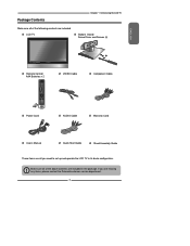
... CH PAGE MUTE ASPECT LAST GUIDE LIVE TV PIP MENU OK INFO CC EXIT DVR 1 2 3 ABC DEF 4 5 6 GHI JKL MNO 7 8 9 PQRS TUV WXYZ INPUT . 0 ENTER Power Cord VIDEO Cable Component Cable AUDIO Cable Warranty Card User's Manual Quick Start Guide Stand Assembly Guide These items are included. Package Contents Chapter 1 Introducing... the LCD TV Make sure all of the following contents are all of the above contents are missing any items, please contact the Polaroid customer service department. 7
... CH PAGE MUTE ASPECT LAST GUIDE LIVE TV PIP MENU OK INFO CC EXIT DVR 1 2 3 ABC DEF 4 5 6 GHI JKL MNO 7 8 9 PQRS TUV WXYZ INPUT . 0 ENTER Power Cord VIDEO Cable Component Cable AUDIO Cable Warranty Card User's Manual Quick Start Guide Stand Assembly Guide These items are included. Package Contents Chapter 1 Introducing... the LCD TV Make sure all of the following contents are all of the above contents are missing any items, please contact the Polaroid customer service department. 7
User Manual
Page 12
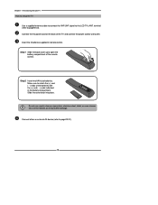
... ends of the batteries with the (+) and ( - ) ends indicated in remote control. Make sure to open the battery compartment of the TV and connect the power cord to page23-31). 10 Do not use caustic cleaners (porcelain, stainless steel, toilet, or oven cleaner etc.) on the remote, as it may suffer... damage. Connect the AC power cord at the back of the remote control. Insert the 2 batteries supplied in the battery compartment. Connect other an external AV device (refer to wall...
... ends of the batteries with the (+) and ( - ) ends indicated in remote control. Make sure to open the battery compartment of the TV and connect the power cord to page23-31). 10 Do not use caustic cleaners (porcelain, stainless steel, toilet, or oven cleaner etc.) on the remote, as it may suffer... damage. Connect the AC power cord at the back of the remote control. Insert the 2 batteries supplied in the battery compartment. Connect other an external AV device (refer to wall...

User Manual
Page 15
... other AV equipment with VGA and AUDIO(L/R) output jacks. The AUDIO(L/R) of HDMI IN is for DVI connection. AUDIO OUT-STEREO Connects to the AC power cord. 13 AC IN Connects to the AUDIO(L/R) input jacks on AV equipment. Rear View and Jacks Chapter 1 Introducing the LCD TV ENGLISH VIDEO2 IN...
... other AV equipment with VGA and AUDIO(L/R) output jacks. The AUDIO(L/R) of HDMI IN is for DVI connection. AUDIO OUT-STEREO Connects to the AC power cord. 13 AC IN Connects to the AUDIO(L/R) input jacks on AV equipment. Rear View and Jacks Chapter 1 Introducing the LCD TV ENGLISH VIDEO2 IN...

User Manual
Page 20
... an Antenna Antenna Connection The antenna requirements for good color TV reception are completed. The following is a brief explanation of the type of any AC power cords to a 75-ohm terminal through a 300-75-ohm adapter (not included). 300-ohm twin-lead cable (flat) 18 Chapter 2 Installing the LCD TV Chapter...
... an Antenna Antenna Connection The antenna requirements for good color TV reception are completed. The following is a brief explanation of the type of any AC power cords to a 75-ohm terminal through a 300-75-ohm adapter (not included). 300-ohm twin-lead cable (flat) 18 Chapter 2 Installing the LCD TV Chapter...

User Manual
Page 23
...for switching the LCD TV into standby, it does not disconnect the device from the main voltage. The POWER button on the front panel is designed to protect your TV. Press the button on the LCD TV.... In the event of an electrical storm or power outage the safety fuse is only used for a 4A 250V - 5x20mm Time Lag Fuse (Slow Blow) to ...long period of time. HDTV/TV AIR/CABLE VHF/UHF IN This TV is blown, visit your TV has no power, check the fuse by prying the cover off, following the illustration below. If the fuse is equipped with a ...
...for switching the LCD TV into standby, it does not disconnect the device from the main voltage. The POWER button on the front panel is designed to protect your TV. Press the button on the LCD TV.... In the event of an electrical storm or power outage the safety fuse is only used for a 4A 250V - 5x20mm Time Lag Fuse (Slow Blow) to ...long period of time. HDTV/TV AIR/CABLE VHF/UHF IN This TV is blown, visit your TV has no power, check the fuse by prying the cover off, following the illustration below. If the fuse is equipped with a ...
User Manual
Page 25
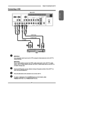
METHOD B: Use an audio cable to connect the VCR's audio output jacks to the LCD TV's VIDEO2 IN jacks. Connect all AC power sources, before turning on the LCD TV. Connecting a VCR Rear of the LCD TV or other connected equipment. Press the button on the remote to ...select VIDEO2( METHOD A), or VIDEO3 (METHOD B). 23 To watch a videotape, press the INPUT button on the remote to turn on the power switch of TV Chapter 2 Installing the LCD TV ENGLISH AV Cable AUDIO Cable S-VIDEO Cable A B METHOD A: Use a composite cable to connect the VCR's composite video...
METHOD B: Use an audio cable to connect the VCR's audio output jacks to the LCD TV's VIDEO2 IN jacks. Connect all AC power sources, before turning on the LCD TV. Connecting a VCR Rear of the LCD TV or other connected equipment. Press the button on the remote to ...select VIDEO2( METHOD A), or VIDEO3 (METHOD B). 23 To watch a videotape, press the INPUT button on the remote to turn on the power switch of TV Chapter 2 Installing the LCD TV ENGLISH AV Cable AUDIO Cable S-VIDEO Cable A B METHOD A: Use a composite cable to connect the VCR's composite video...
User Manual
Page 26
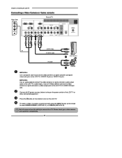
... an S-Video cable to connect the video camera's or game console's s-video output jack to the LCD TV's audio inputs. Not all AC power sources, before turning on the power switch of TV VIDEO L R VIDEO1 IN AUDIO Cable or S-VIDEO Cable GAME CONSOLE B AV Cable A METHOD A: Use a composite cable to connect the...
... an S-Video cable to connect the video camera's or game console's s-video output jack to the LCD TV's audio inputs. Not all AC power sources, before turning on the power switch of TV VIDEO L R VIDEO1 IN AUDIO Cable or S-VIDEO Cable GAME CONSOLE B AV Cable A METHOD A: Use a composite cable to connect the...
User Manual
Page 28
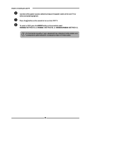
For best picture quality, if your equipment has component video output, use a component cable instead of the LCD TV or other connected equipment. Chapter 2 Installing the LCD TV Connect all AC power sources, before turning on the power switch of a composite video or S-video cable. 26 Press the button on the LCD TV. To watch a DVD, press the INPUT button on the remote to turn on the remote to select VIDEO2( METHOD A), or VIDEO3 ( METHOD B), or VIDEO4/VIDEO5 (METHOD C).
For best picture quality, if your equipment has component video output, use a component cable instead of the LCD TV or other connected equipment. Chapter 2 Installing the LCD TV Connect all AC power sources, before turning on the power switch of a composite video or S-video cable. 26 Press the button on the LCD TV. To watch a DVD, press the INPUT button on the remote to turn on the remote to select VIDEO2( METHOD A), or VIDEO3 ( METHOD B), or VIDEO4/VIDEO5 (METHOD C).
User Manual
Page 29
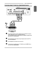
... LCD TV Connecting a Digital TV Cable Box or Digital Satellite Receiver Rear of the LCD TV or other connected equipment. Connect all AC power sources, before turning on the power switch of TV Pb Pr COMPONENT/AUDIO Cable Pb Pr Use a component cable to connect the satellite receiver's/TV Cable Box's component...
... LCD TV Connecting a Digital TV Cable Box or Digital Satellite Receiver Rear of the LCD TV or other connected equipment. Connect all AC power sources, before turning on the power switch of TV Pb Pr COMPONENT/AUDIO Cable Pb Pr Use a component cable to connect the satellite receiver's/TV Cable Box's component...
User Manual
Page 30
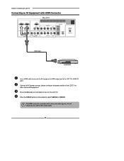
Chapter 2 Installing the LCD TV Connecting an AV Equipment with HDMI Connector Rear of the LCD TV or other connected equipment. The HDMI connector provides both video and audio signals, it's not necessary to turn on the remote to connect the audio cable. 28 Press the button on the LCD TV. Press the INPUT button on the power switch of TV HDMI Cable AV EQUIPMENT Use a HDMI cable to connect the AV equipment's HDMI output jack to select VIDEO6 or VIDEO7. Connect all AC power sources, before turning on the remote to the LCD TV's HDMI IN jacks.
Chapter 2 Installing the LCD TV Connecting an AV Equipment with HDMI Connector Rear of the LCD TV or other connected equipment. The HDMI connector provides both video and audio signals, it's not necessary to turn on the remote to connect the audio cable. 28 Press the button on the LCD TV. Press the INPUT button on the power switch of TV HDMI Cable AV EQUIPMENT Use a HDMI cable to connect the AV equipment's HDMI output jack to select VIDEO6 or VIDEO7. Connect all AC power sources, before turning on the remote to the LCD TV's HDMI IN jacks.
User Manual
Page 31
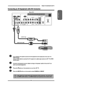
... 2 Installing the LCD TV Connecting an AV Equipment with DVI Connector Rear of the LCD TV or other connected equipment. Connect all AC power sources, before turning on the power switch of TV ENGLISH AUDIO Cable HDMI-to-DVI Cable AUDIO L R DVI IN AV EQUIPMENT Use a HDMI-to-DVI cable to connect...
... 2 Installing the LCD TV Connecting an AV Equipment with DVI Connector Rear of the LCD TV or other connected equipment. Connect all AC power sources, before turning on the power switch of TV ENGLISH AUDIO Cable HDMI-to-DVI Cable AUDIO L R DVI IN AV EQUIPMENT Use a HDMI-to-DVI cable to connect...
User Manual
Page 32
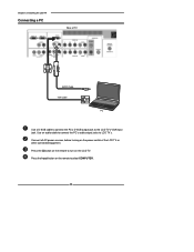
Use an audio cable to connect the PC's audio output jacks to the LCD TV's VGA input jack. Press the button on the remote to turn on the remote to select COMPUTER. 30 Press the Input button on the LCD TV. Connect all AC power sources, before turning on the power switch of TV AUDIO Cable VGA Cable PC Use a D-SUB cable to connect the PC's D-SUB output jack to LCD TV's. Chapter 2 Installing the LCD TV Connecting a PC Rear of the LCD TV or other connected equipment.
Use an audio cable to connect the PC's audio output jacks to the LCD TV's VGA input jack. Press the button on the remote to turn on the remote to select COMPUTER. 30 Press the Input button on the LCD TV. Connect all AC power sources, before turning on the power switch of TV AUDIO Cable VGA Cable PC Use a D-SUB cable to connect the PC's D-SUB output jack to LCD TV's. Chapter 2 Installing the LCD TV Connecting a PC Rear of the LCD TV or other connected equipment.
User Manual
Page 33
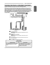
... Stereo System, please follow the instructions below. Variable Audio Fixed Audio The audio output from your TV is fixed. Connect all AC power sources, before turning on the power switch of the LCD TV or other AV equipment. The audio output on the LCD TV. ENGLISH Chapter 2 Installing the LCD TV...
... Stereo System, please follow the instructions below. Variable Audio Fixed Audio The audio output from your TV is fixed. Connect all AC power sources, before turning on the power switch of the LCD TV or other AV equipment. The audio output on the LCD TV. ENGLISH Chapter 2 Installing the LCD TV...
User Manual
Page 57
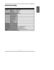
Resolution 1366x768 Input Connector VIDEO/AUDIO(L/R) 2 S-VIDEO/AUDIO(L/R) 1 YPbPr/AUDIO(L/R) 2 VGA/AUDIO(L/R) 1 HDMI/AUDIO(L/R) 2 AUDIO OUT(L/R) 1 COAXIAL 1 HEADPHONE 1 Built-in DVD 1 USB Connector 1 SD Card Reader 1 Power Source AC110~220V, 50/60HZ, 2.2A Power Consumption 180 W, standby < 1 W Dimension 27.30 w x 21.78 h x 3.86 d inches WEIGHT 34.94 LB Specifications 55 ENGLISH SPECIFICATIONS LCD Panel Panel Size 26" TFT LCD Brightness 500 cm2 Contrast Ratio 800:1 Max.
Resolution 1366x768 Input Connector VIDEO/AUDIO(L/R) 2 S-VIDEO/AUDIO(L/R) 1 YPbPr/AUDIO(L/R) 2 VGA/AUDIO(L/R) 1 HDMI/AUDIO(L/R) 2 AUDIO OUT(L/R) 1 COAXIAL 1 HEADPHONE 1 Built-in DVD 1 USB Connector 1 SD Card Reader 1 Power Source AC110~220V, 50/60HZ, 2.2A Power Consumption 180 W, standby < 1 W Dimension 27.30 w x 21.78 h x 3.86 d inches WEIGHT 34.94 LB Specifications 55 ENGLISH SPECIFICATIONS LCD Panel Panel Size 26" TFT LCD Brightness 500 cm2 Contrast Ratio 800:1 Max.


