Service Manual
Page 5
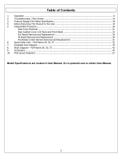
Troubleshooting / Flow Charts ...14 3. FLM-Series 26, 32, 37 32 7. FLM-Series 26, 32, 37 42 9. Table of Contents 1. Go to polaroid.com to the User 19 5. Before Returning This Product to obtain User Manual. 5 Schematics ...43 10. Polaroid Display Cell Defect Specification 18 4. Disassembly Procedure...20 Rear Cover Removal ...21 Rear Cabinet Cover LCD Panel and Front...
Troubleshooting / Flow Charts ...14 3. FLM-Series 26, 32, 37 32 7. FLM-Series 26, 32, 37 42 9. Table of Contents 1. Go to polaroid.com to the User 19 5. Before Returning This Product to obtain User Manual. 5 Schematics ...43 10. Polaroid Display Cell Defect Specification 18 4. Disassembly Procedure...20 Rear Cover Removal ...21 Rear Cabinet Cover LCD Panel and Front...
Service Manual
Page 21
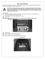
...item 3) (6) Remove control box cover- Use protective cloth between work bench and TV front. Stand Removal (1) Lay TV flat on workbench. Allow time for power within all system boards to protect the front bezel and LCD screen from being scratched. slide toward bottom of any objects into the vent holes ...removed from being scratched. Be careful to protect the front bezel and LCD screen from the wall outlet. Never insert any part the TV, make sure the power is OFF, and the power cord is a 26" model. 32" and 37" models will have different stand screw quantities and locations. Note: ...
...item 3) (6) Remove control box cover- Use protective cloth between work bench and TV front. Stand Removal (1) Lay TV flat on workbench. Allow time for power within all system boards to protect the front bezel and LCD screen from being scratched. slide toward bottom of any objects into the vent holes ...removed from being scratched. Be careful to protect the front bezel and LCD screen from the wall outlet. Never insert any part the TV, make sure the power is OFF, and the power cord is a 26" model. 32" and 37" models will have different stand screw quantities and locations. Note: ...
Service Manual
Page 23
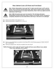
...is completely detached from the wall outlet. Rear Cabinet Cover LCD Panel and Front Bezel Note: Before disassembly of 2, 3, 4, B, C, D (3) Remove screws which fasten rear cabinet to front frame (PIC1) in production. Never insert any part the TV, make sure the power is OFF, and the power ...the rear cabinet cover will come off. *NOTE: Pictured is a 26" model. 32" and 37" models will have some different rear cabinet cover screw quantities and locations. 23 The following LCD panel disassembly/removal instructions may not apply to discharge before removing so the bezel is not damaged. ...
...is completely detached from the wall outlet. Rear Cabinet Cover LCD Panel and Front Bezel Note: Before disassembly of 2, 3, 4, B, C, D (3) Remove screws which fasten rear cabinet to front frame (PIC1) in production. Never insert any part the TV, make sure the power is OFF, and the power ...the rear cabinet cover will come off. *NOTE: Pictured is a 26" model. 32" and 37" models will have some different rear cabinet cover screw quantities and locations. 23 The following LCD panel disassembly/removal instructions may not apply to discharge before removing so the bezel is not damaged. ...

Service Manual
Page 32
...the Polaroid serial number format breakdown with R. Below is replaced with a sample serial number. C0600012720000001 RoHS Compliant Serial Number Example - Spare Parts Lists - Reference the serial number format details below to identify the replacement part(s) needed for this model. In the event the TV ...perform a clear or reset in the spare part lists with multiple versions. Service bulletins can be obtained through your Polaroid service contact. FLM-Series 26, 32, 37 Attention Service Centers Some models consist of Production Model Version SAMPLE SERIAL NUMBER FORMAT - 6.
...the Polaroid serial number format breakdown with R. Below is replaced with a sample serial number. C0600012720000001 RoHS Compliant Serial Number Example - Spare Parts Lists - Reference the serial number format details below to identify the replacement part(s) needed for this model. In the event the TV ...perform a clear or reset in the spare part lists with multiple versions. Service bulletins can be obtained through your Polaroid service contact. FLM-Series 26, 32, 37 Attention Service Centers Some models consist of Production Model Version SAMPLE SERIAL NUMBER FORMAT - 6.
Service Manual
Page 38
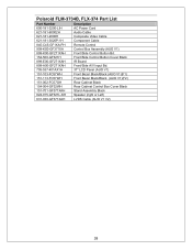
Polaroid FLM-3734B, FLX-374 Part List Part Number Description 600-181-3200-LIH AC Power Cord 621-181-60002H Audio Cable 621-181-2000H Composite Video Cable ... Bd. 154-500-GF321H Front/Side Control Button Cover Black 899-E00-GF271XAH IR Board 899-A00-GF271XAH Front/Side A/V Input Bd. 705-537-401AX1H 37" LCD Panel (AUO V1) 151-103-FC57WH Front Bezel Black/Black (AUO V1)(F1) 151-113-FC57WH Front Bezel Black/Black (AUO V1)(F2) 151-002...
Polaroid FLM-3734B, FLX-374 Part List Part Number Description 600-181-3200-LIH AC Power Cord 621-181-60002H Audio Cable 621-181-2000H Composite Video Cable ... Bd. 154-500-GF321H Front/Side Control Button Cover Black 899-E00-GF271XAH IR Board 899-A00-GF271XAH Front/Side A/V Input Bd. 705-537-401AX1H 37" LCD Panel (AUO V1) 151-103-FC57WH Front Bezel Black/Black (AUO V1)(F1) 151-113-FC57WH Front Bezel Black/Black (AUO V1)(F2) 151-002...
Service Manual
Page 50
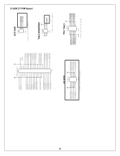
...Series 2X7 (14pin) CON2 PHONE_A_D_O 13 14 11 12 FRONT_A_L_IN 9 10 7 8 FRONT_COMPOSITE 5 6 3 4 FRONT_S_CHROMA 1 2 PHONE_A_L_O PHONE_A_R_O FRONT_A_R_IN FRONT_S_LUMA 200PHD-14LT AUX AV D-SUB 37 PIN Board 5 0 200PHD Series 2X4 (8pin) CON3 VBLON ADJ_INV 7 8 5 6 3 4 1 2 200PHD-8LT INVERTER CTRL. 250XH Series 1X4 (4pin) CON4 SPK_L_OUT- 4... OUT SPK_L_OUT+ SPK_L_OUTPHONE_A_D_O FRONT_A_L_IN FRONT_COMPOSITE FRONT_S_CHROMA SW6-VOL-UP SW4-CH-UP SW2-SOURCE LED_G IR-OUT LTDC_INT LTDC_DATA VCCSB J1 19 37 18 36 17 35 16 34 15 33 14 32 13 31 12 30 11 29 10 28 9 27 8 26 7...
...Series 2X7 (14pin) CON2 PHONE_A_D_O 13 14 11 12 FRONT_A_L_IN 9 10 7 8 FRONT_COMPOSITE 5 6 3 4 FRONT_S_CHROMA 1 2 PHONE_A_L_O PHONE_A_R_O FRONT_A_R_IN FRONT_S_LUMA 200PHD-14LT AUX AV D-SUB 37 PIN Board 5 0 200PHD Series 2X4 (8pin) CON3 VBLON ADJ_INV 7 8 5 6 3 4 1 2 200PHD-8LT INVERTER CTRL. 250XH Series 1X4 (4pin) CON4 SPK_L_OUT- 4... OUT SPK_L_OUT+ SPK_L_OUTPHONE_A_D_O FRONT_A_L_IN FRONT_COMPOSITE FRONT_S_CHROMA SW6-VOL-UP SW4-CH-UP SW2-SOURCE LED_G IR-OUT LTDC_INT LTDC_DATA VCCSB J1 19 37 18 36 17 35 16 34 15 33 14 32 13 31 12 30 11 29 10 28 9 27 8 26 7...

