
Service Manual
Page 2
... personnel. (14) Unplug this product where people will only fit into a grounding-type power outlet. The product may touch dangerous voltage points or short out parts that the total of the ampere ratings on the product plugged into the extension cord does not exceed 15 ampere. (12) Never push objects of...
... personnel. (14) Unplug this product where people will only fit into a grounding-type power outlet. The product may touch dangerous voltage points or short out parts that the total of the ampere ratings on the product plugged into the extension cord does not exceed 15 ampere. (12) Never push objects of...
Service Manual
Page 3
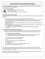
...- SnAgCu (shall not be performed only by their antistatic bags only when you are ready to a bare metal part of antistatic bags because only the inside an LCD or plasma TV are sensitive to damage or a short, which could result in board assembly: e1 - SnZn, SnZnx (no Sn... matches the symbol on board and components within this time. Important Service and Safety Information Service work should be included in the TV case! Because the melting point of the bags provide electrostatic protection. • Always hold components by qualified service technicians familiar with...
...- SnAgCu (shall not be performed only by their antistatic bags only when you are ready to a bare metal part of antistatic bags because only the inside an LCD or plasma TV are sensitive to damage or a short, which could result in board assembly: e1 - SnZn, SnZnx (no Sn... matches the symbol on board and components within this time. Important Service and Safety Information Service work should be included in the TV case! Because the melting point of the bags provide electrostatic protection. • Always hold components by qualified service technicians familiar with...

Service Manual
Page 4
... enough to those originally used in the television. (1) Always use , clean the bit with steel wool or fine sandpaper. (0) NOTICE ABOUT REPLACEMENT PARTS Many electrical and mechanical parts within LCD or plasma televisions are chosen for their specific safety characteristics within the overall system. If a different type of the soldering bit may be...
... enough to those originally used in the television. (1) Always use , clean the bit with steel wool or fine sandpaper. (0) NOTICE ABOUT REPLACEMENT PARTS Many electrical and mechanical parts within LCD or plasma televisions are chosen for their specific safety characteristics within the overall system. If a different type of the soldering bit may be...
Service Manual
Page 5
... This Product to obtain User Manual. 5 FLM-Series 26, 32, 37 32 7. Block Diagram - Troubleshooting / Flow Charts ...14 3. Exploded View Diagram ...39 8. Go to polaroid.com to the User 19 5. Polaroid Display Cell Defect Specification 18 4. PCB Layout Diagrams ...51 Model Specifications are located in User Manual. Operation ...6 2. Spare Parts Lists - Schematics ...43 10. Disassembly...
... This Product to obtain User Manual. 5 FLM-Series 26, 32, 37 32 7. Block Diagram - Troubleshooting / Flow Charts ...14 3. Exploded View Diagram ...39 8. Go to polaroid.com to the User 19 5. Polaroid Display Cell Defect Specification 18 4. PCB Layout Diagrams ...51 Model Specifications are located in User Manual. Operation ...6 2. Spare Parts Lists - Schematics ...43 10. Disassembly...
Service Manual
Page 14
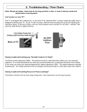
...and Component 2 as the input sources. 14 The master password can't be changed and should be used first before ordering parts. If the fuse is recommended that you loose your TV has no power, check the fuse by AC plug, perform a clear or reset in factory mode and retest before ...setting your TV? Troubleshooting / Flow Charts Note: Reseat all passwords. It is blown, visit your TV. In the event of an electrical storm or power outage the safety fuse is 8202. This TV is 0000. In the event you keep your Parental Controls...
...and Component 2 as the input sources. 14 The master password can't be changed and should be used first before ordering parts. If the fuse is recommended that you loose your TV has no power, check the fuse by AC plug, perform a clear or reset in factory mode and retest before ...setting your TV? Troubleshooting / Flow Charts Note: Reseat all passwords. It is blown, visit your TV. In the event of an electrical storm or power outage the safety fuse is 8202. This TV is 0000. In the event you keep your Parental Controls...

Service Manual
Page 19
... 1.5k ohm, 10 watt resistor paralleled by a 0.15 µF capacitor. b. Measurement points can vary slightly even between the chassis or any metal parts. (2) Inspect all wiring to be sure no wires are pinched between revisions of the same model, so always conduct a thorough review of the chassis ... cord directly into a 120 V AC outlet. A non-polarized adapter is required to locate metal points that no shock hazard exists on any part of 0.375 Vrms AC (0.25 mArms) or higher indicates a potential shock hazard. Before Returning This Product to the User Before returning this product...
... 1.5k ohm, 10 watt resistor paralleled by a 0.15 µF capacitor. b. Measurement points can vary slightly even between the chassis or any metal parts. (2) Inspect all wiring to be sure no wires are pinched between revisions of the same model, so always conduct a thorough review of the chassis ... cord directly into a 120 V AC outlet. A non-polarized adapter is required to locate metal points that no shock hazard exists on any part of 0.375 Vrms AC (0.25 mArms) or higher indicates a potential shock hazard. Before Returning This Product to the User Before returning this product...

Service Manual
Page 20
...surface. • Wear a grounding wrist strap (available at most electronics stores) and attach it to a bare metal part of antistatic bags because only the inside an LCD or plasma TV are sensitive to avoid damaging the cable. • Use a magnetized screwdriver for power within all system boards to ...discharge before touching any part the TV, make sure the power is OFF, and the power cord is large enough...
...surface. • Wear a grounding wrist strap (available at most electronics stores) and attach it to a bare metal part of antistatic bags because only the inside an LCD or plasma TV are sensitive to avoid damaging the cable. • Use a magnetized screwdriver for power within all system boards to ...discharge before touching any part the TV, make sure the power is OFF, and the power cord is large enough...
Service Manual
Page 21
.... Be careful to protect the front bezel and LCD screen from being scratched. Use protective cloth between work bench and TV front. Stand Removal (1) Lay TV flat on workbench. Note: Before disassembly of TV and lift off. 21 Never insert any part the TV, make sure the power is OFF, and the... power cord is a 26" model. 32" and 37" models will have different stand screw...
.... Be careful to protect the front bezel and LCD screen from being scratched. Use protective cloth between work bench and TV front. Stand Removal (1) Lay TV flat on workbench. Note: Before disassembly of TV and lift off. 21 Never insert any part the TV, make sure the power is OFF, and the... power cord is a 26" model. 32" and 37" models will have different stand screw...
Service Manual
Page 23
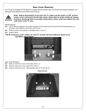
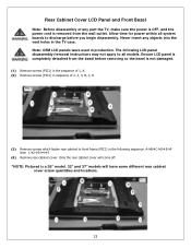
...Allow time for power within all system boards to all models. Never insert any part the TV, make sure the power is OFF, and the power cord is removed from the bezel before you begin disassembly. Rear Cabinet Cover LCD Panel and Front Bezel Note: Before disassembly of 2, 3, 4, B, C, D... (3) Remove screws which fasten rear cabinet to front frame (PIC1) in the following LCD panel disassembly/removal instructions may not apply to discharge before removing so the bezel is a 26" model. 32" and 37" models will come off. *NOTE: Pictured is not damaged. (1) Remove screws (PIC1) in the...
...Allow time for power within all system boards to all models. Never insert any part the TV, make sure the power is OFF, and the power cord is removed from the bezel before you begin disassembly. Rear Cabinet Cover LCD Panel and Front Bezel Note: Before disassembly of 2, 3, 4, B, C, D... (3) Remove screws which fasten rear cabinet to front frame (PIC1) in the following LCD panel disassembly/removal instructions may not apply to discharge before removing so the bezel is a 26" model. 32" and 37" models will come off. *NOTE: Pictured is not damaged. (1) Remove screws (PIC1) in the...

Service Manual
Page 29
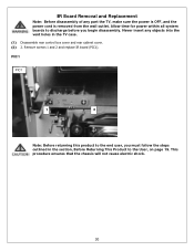
... that the chassis will not cause electric shock. 29 A/V Board Removal and Replacement Note: Before disassembly of any objects into the vent holes in the TV case. (1) Disassemble control box cover and rear cabinet cover and remove A/V assembly. (2) Using a small pair of the A/V assembly. (3) Slide out A/V board and replace (...PIC2 Note: Before returning this product to the User, on page 19. Locking tabl should only pivot about 45 degrees. Never insert any part the TV, make sure the power is OFF, and the power cord is removed from the wall outlet. Allow time for the opposite side of wire...
... that the chassis will not cause electric shock. 29 A/V Board Removal and Replacement Note: Before disassembly of any objects into the vent holes in the TV case. (1) Disassemble control box cover and rear cabinet cover and remove A/V assembly. (2) Using a small pair of the A/V assembly. (3) Slide out A/V board and replace (...PIC2 Note: Before returning this product to the User, on page 19. Locking tabl should only pivot about 45 degrees. Never insert any part the TV, make sure the power is OFF, and the power cord is removed from the wall outlet. Allow time for the opposite side of wire...
Service Manual
Page 30
... (PIC1). Allow time for power within all system boards to discharge before you must follow the steps outlined in the TV case. (1) Disassemble rear control box cover and rear cabinet cover. (2) 2. Never insert any part the TV, make sure the power is OFF, and the power cord is removed from the wall outlet.
... (PIC1). Allow time for power within all system boards to discharge before you must follow the steps outlined in the TV case. (1) Disassemble rear control box cover and rear cabinet cover. (2) 2. Never insert any part the TV, make sure the power is OFF, and the power cord is removed from the wall outlet.

Service Manual
Page 31
... the chassis will not cause electric shock. 31 PIC1 Note: Before returning this product to discharge before you must follow the steps outlined in the TV case. (1) Disassemble control box cover and rear cabinet cover. (2) The control button board is removed from the wall outlet. Front/Side Control Buttons...Replacement Note: Before disassembly of any objects into the vent holes in the section, Before Returning This Product to front bezel. Never insert any part the TV, make sure the power is OFF, and the power cord is attached with glue. Use alcohol to soften the glue and remove the ...
... the chassis will not cause electric shock. 31 PIC1 Note: Before returning this product to discharge before you must follow the steps outlined in the TV case. (1) Disassemble control box cover and rear cabinet cover. (2) The control button board is removed from the wall outlet. Front/Side Control Buttons...Replacement Note: Before disassembly of any objects into the vent holes in the section, Before Returning This Product to front bezel. Never insert any part the TV, make sure the power is OFF, and the power cord is attached with glue. Use alcohol to soften the glue and remove the ...

Service Manual
Page 32
FLM-Series 26, 32, 37 Attention Service Centers Some models consist of parts with an asterisk (*) are multiple version parts. Service bulletins can be obtained through your Polaroid service contact. Replacement parts in the part lists please review service bulletins for repair. The TV serial number Model Version is not present in the spare part lists with multiple versions. DETAILS...
FLM-Series 26, 32, 37 Attention Service Centers Some models consist of parts with an asterisk (*) are multiple version parts. Service bulletins can be obtained through your Polaroid service contact. Replacement parts in the part lists please review service bulletins for repair. The TV serial number Model Version is not present in the spare part lists with multiple versions. DETAILS...
Service Manual
Page 38
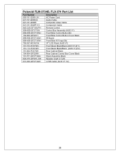
Polaroid FLM-3734B, FLX-374 Part List Part Number Description 600-181-3200-LIH AC Power Cord 621-181-60002H Audio Cable 621-181-2000H Composite Video Cable 621-181-3020P-1H Component ... Bd. 154-500-GF321H Front/Side Control Button Cover Black 899-E00-GF271XAH IR Board 899-A00-GF271XAH Front/Side A/V Input Bd. 705-537-401AX1H 37" LCD Panel (AUO V1) 151-103-FC57WH Front Bezel Black/Black (AUO V1)(F1) 151-113-FC57WH Front Bezel Black/Black (AUO V1)(F2) 151-002...
Polaroid FLM-3734B, FLX-374 Part List Part Number Description 600-181-3200-LIH AC Power Cord 621-181-60002H Audio Cable 621-181-2000H Composite Video Cable 621-181-3020P-1H Component ... Bd. 154-500-GF321H Front/Side Control Button Cover Black 899-E00-GF271XAH IR Board 899-A00-GF271XAH Front/Side A/V Input Bd. 705-537-401AX1H 37" LCD Panel (AUO V1) 151-103-FC57WH Front Bezel Black/Black (AUO V1)(F1) 151-113-FC57WH Front Bezel Black/Black (AUO V1)(F2) 151-002...


