Service Manual
Page 21
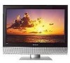
...of TV and lift off. 21 www.polaroid.com Allow time for power within all system boards to protect the front bezel and LCD screen from being scratched. Never insert any part the TV, make sure the power is OFF, and the power cord is a 26"... model. 32" and 37" models will have different stand screw quantities and locations. Rear Cover Removal (4) Remove control box cover screws (PIC1 item 1, 2) (5) Remove control box cover screws (PIC1 item 3) (6) Remove control box...
...of TV and lift off. 21 www.polaroid.com Allow time for power within all system boards to protect the front bezel and LCD screen from being scratched. Never insert any part the TV, make sure the power is OFF, and the power cord is a 26"... model. 32" and 37" models will have different stand screw quantities and locations. Rear Cover Removal (4) Remove control box cover screws (PIC1 item 1, 2) (5) Remove control box cover screws (PIC1 item 3) (6) Remove control box...

Service Manual
Page 22
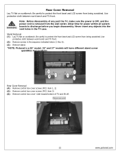
... the Aluminum foil covering the LVDS connector. Release control box from back hinges and tilt to the User, on page 19. There are connected so be careful. Disconnect LVDS cable connector from LCD panel (PIC2). (9) Disconnect the LCD Panel power cord from the A/V connector side (PIC1...). This procedure ensures that are cables underneath that the chassis will not cause electric shock. 22 www.polaroid.com (7) Lift up the control box from bottom side of control box (PIC3).
... the Aluminum foil covering the LVDS connector. Release control box from back hinges and tilt to the User, on page 19. There are connected so be careful. Disconnect LVDS cable connector from LCD panel (PIC2). (9) Disconnect the LCD Panel power cord from the A/V connector side (PIC1...). This procedure ensures that are cables underneath that the chassis will not cause electric shock. 22 www.polaroid.com (7) Lift up the control box from bottom side of control box (PIC3).
Service Manual
Page 29
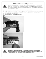
...Allow time for the opposite side of the A/V assembly. (3) Slide out A/V board and replace (PIC2). (4) Push locking tabs in the TV case. (1) Disassemble control box cover and rear cabinet cover and remove A/V assembly. (2) Using a small pair of any objects into the vent holes in to the end... user, you begin disassembly. This procedure ensures that the chassis will not cause electric shock. 29 www.polaroid.com Locking tabl should...
...Allow time for the opposite side of the A/V assembly. (3) Slide out A/V board and replace (PIC2). (4) Push locking tabs in the TV case. (1) Disassemble control box cover and rear cabinet cover and remove A/V assembly. (2) Using a small pair of any objects into the vent holes in to the end... user, you begin disassembly. This procedure ensures that the chassis will not cause electric shock. 29 www.polaroid.com Locking tabl should...
Service Manual
Page 30
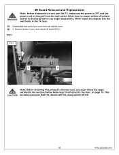
... boards to discharge before you must follow the steps outlined in the TV case. (1) Disassemble rear control box cover and rear cabinet cover. (2) 2. This procedure ensures that the chassis will not cause electric shock. 30 www.polaroid.com Never insert any part the TV, make sure the power is OFF, and the power cord is...
... boards to discharge before you must follow the steps outlined in the TV case. (1) Disassemble rear control box cover and rear cabinet cover. (2) 2. This procedure ensures that the chassis will not cause electric shock. 30 www.polaroid.com Never insert any part the TV, make sure the power is OFF, and the power cord is...

Service Manual
Page 31
...the chassis will not cause electric shock. 31 www.polaroid.com Allow time for power within all system boards to discharge before you must follow the steps outlined in the TV case. (1) Disassemble control box cover and rear cabinet cover. (2) The control button board is removed from the wall outlet. ...Never insert any part the TV, make sure the power is OFF, and the power cord is ...
...the chassis will not cause electric shock. 31 www.polaroid.com Allow time for power within all system boards to discharge before you must follow the steps outlined in the TV case. (1) Disassemble control box cover and rear cabinet cover. (2) The control button board is removed from the wall outlet. ...Never insert any part the TV, make sure the power is OFF, and the power cord is ...
Service Manual
Page 35
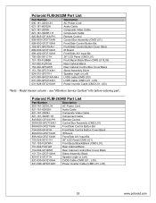
...-A00-GF271XAH Front/Side A/V Input Bd. 705-526-051C-1H 26" LCD Panel (CMO L01) 151-103-FL98BH Front Bezel Black/Silver (CMO L01/L03) 151-002-FL97GH Rear Cabinet Black 154-004-GF32WH Rear Cabinet Control Box Cover Black 151-700-GF271XAH Stand Assembly Silver 824-015-GF271H Speaker..." info before ordering part. Polaroid FLM-2634B Part List Part Number Description 600-181-3200-LIH AC Power Cord 621-181-60002H Audio Cable 621-181-2000H Composite Video Cable 621-181-3020P-1H Component Cable 845-B45-GF1XA-PH Remote Control 909-KS0-GF271XAH Control Box Assembly (CMO L01) 899...
...-A00-GF271XAH Front/Side A/V Input Bd. 705-526-051C-1H 26" LCD Panel (CMO L01) 151-103-FL98BH Front Bezel Black/Silver (CMO L01/L03) 151-002-FL97GH Rear Cabinet Black 154-004-GF32WH Rear Cabinet Control Box Cover Black 151-700-GF271XAH Stand Assembly Silver 824-015-GF271H Speaker..." info before ordering part. Polaroid FLM-2634B Part List Part Number Description 600-181-3200-LIH AC Power Cord 621-181-60002H Audio Cable 621-181-2000H Composite Video Cable 621-181-3020P-1H Component Cable 845-B45-GF1XA-PH Remote Control 909-KS0-GF271XAH Control Box Assembly (CMO L01) 899...
Service Manual
Page 38
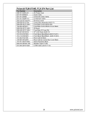
Polaroid FLM-3734B, FLX-374 Part List Part Number Description 600-181-3200-LIH AC Power Cord 621-181-60002H Audio Cable 621-181-2000H Composite Video Cable 621-181-3020P-1H Component Cable 845-C45-GF1XA-PH Remote Control 909-KS0-GF371XA Control Box Assembly (AUO V1) 899-K00-GF271XAH Front/Side Control...Input Bd. 705-537-401AX1H 37" LCD Panel (AUO V1) 151-103-FC57WH Front Bezel Black/Black (AUO V1)(F1) 151-113-FC57WH Front Bezel Black/Black (AUO V1)(F2) 151-002-FC57GH Rear Cabinet Black 154-004-GF32WH Rear Cabinet Control Box Cover Black 151-701-GF371XAH Stand Assembly...
Polaroid FLM-3734B, FLX-374 Part List Part Number Description 600-181-3200-LIH AC Power Cord 621-181-60002H Audio Cable 621-181-2000H Composite Video Cable 621-181-3020P-1H Component Cable 845-C45-GF1XA-PH Remote Control 909-KS0-GF371XA Control Box Assembly (AUO V1) 899-K00-GF271XAH Front/Side Control...Input Bd. 705-537-401AX1H 37" LCD Panel (AUO V1) 151-103-FC57WH Front Bezel Black/Black (AUO V1)(F1) 151-113-FC57WH Front Bezel Black/Black (AUO V1)(F2) 151-002-FC57GH Rear Cabinet Black 154-004-GF32WH Rear Cabinet Control Box Cover Black 151-701-GF371XAH Stand Assembly...
User Guide
Page 6
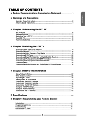
... Contents...7 Setting Up Your LCD TV 8 Your LCD TV...10 Your Remote Control 12 Chapter 2 Installing the LCD TV Connecting a TV Cable or an Antenna 14 Connecting a VCR...18 Connecting a Video Camera or Play Station 19 Connecting a DVD Player 20 Connecting a Digital TV Cable Box or Digital Satellite Receiver 22... Connecting an AV Equipment with HDMI Connector 23 Connecting an AV Equipment with DVI Connector 24 Connecting a PC...25 Connecting an Audio Receiver or a Dolby Digital 5.1 Sound System 26 Chapter 3 USING THE ...
... Contents...7 Setting Up Your LCD TV 8 Your LCD TV...10 Your Remote Control 12 Chapter 2 Installing the LCD TV Connecting a TV Cable or an Antenna 14 Connecting a VCR...18 Connecting a Video Camera or Play Station 19 Connecting a DVD Player 20 Connecting a Digital TV Cable Box or Digital Satellite Receiver 22... Connecting an AV Equipment with HDMI Connector 23 Connecting an AV Equipment with DVI Connector 24 Connecting a PC...25 Connecting an Audio Receiver or a Dolby Digital 5.1 Sound System 26 Chapter 3 USING THE ...


