

Owner's Manual
Page 8
... you start 10 Introduction 10 - Trademarks and licenses 20 Remote control 22 Front panel 23 Rear panel 23 - Additional notes on speaker for HTZ-BD32 28 - Wall mounting the speaker for HTZ-BD52 25 - Wired network connection 41 - Connecting the USB device 3 Getting Started 46 Making settings using the Setup Navigator menu 47 Operating the TV...
... you start 10 Introduction 10 - Trademarks and licenses 20 Remote control 22 Front panel 23 Rear panel 23 - Additional notes on speaker for HTZ-BD32 28 - Wall mounting the speaker for HTZ-BD52 25 - Wired network connection 41 - Connecting the USB device 3 Getting Started 46 Making settings using the Setup Navigator menu 47 Operating the TV...

Owner's Manual
Page 10
... and lower cabinet.) Video cable (1) Battery (2) Remote control (1) FM antenna (1) Screws M4 x 12 (8) (They are used to fix the upper and lower cabinet.) Accessories of speaker box (HTZ-BD32) iPod cradle (1) Power cord • Operating instructions (This document) Non-skid pads (5) Screws M3.5x12 [Taping type] (4) (These screws are used to fix the...
... and lower cabinet.) Video cable (1) Battery (2) Remote control (1) FM antenna (1) Screws M4 x 12 (8) (They are used to fix the upper and lower cabinet.) Accessories of speaker box (HTZ-BD32) iPod cradle (1) Power cord • Operating instructions (This document) Non-skid pads (5) Screws M3.5x12 [Taping type] (4) (These screws are used to fix the...

Owner's Manual
Page 24
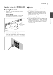
24 Connecting En Chapter 2 Connecting 3. Connect the wires to any other amplifier may result in malfunction or fire. 2. Connection to the player. Non-skid pads Assemble the speakers Speaker setup for HTZ-BD52 2 Preparing the speakers 1. To prevent the risk of each speaker. 3 Insert the upper cabinet to any speakers other than those supplied to this system. •...
24 Connecting En Chapter 2 Connecting 3. Connect the wires to any other amplifier may result in malfunction or fire. 2. Connection to the player. Non-skid pads Assemble the speakers Speaker setup for HTZ-BD52 2 Preparing the speakers 1. To prevent the risk of each speaker. 3 Insert the upper cabinet to any speakers other than those supplied to this system. •...

Owner's Manual
Page 27
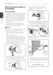
HTZ-BD32 All speakers have a mounting hole which can be used to x the unit to support them. Do not mount on the speaker. Caution • If you intend to mount the speakers on is used to mount on the wall. Before mounting Remember that the speaker system is not responsible for advice. • Pioneer... Connect the wires to the base of each speaker. Make sure that the wall you are not supplied. Use screws suitable for Preparing the speakers 1. to 0.3 in the speaker falling. Connecting 27 En Speaker setup for HTZ-BD32 Wall mounting the speaker for the ...
HTZ-BD32 All speakers have a mounting hole which can be used to x the unit to support them. Do not mount on the speaker. Caution • If you intend to mount the speakers on is used to mount on the wall. Before mounting Remember that the speaker system is not responsible for advice. • Pioneer... Connect the wires to the base of each speaker. Make sure that the wall you are not supplied. Use screws suitable for Preparing the speakers 1. to 0.3 in the speaker falling. Connecting 27 En Speaker setup for HTZ-BD32 Wall mounting the speaker for the ...
Owner's Manual
Page 29
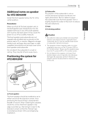
... to the player to three locations Non-skid pad (for front) Non-skid pad (for HTZ-BD92HW Caution Preparing the speakers 1. Attach the non-skid pads to the player. Connect the wires to the base of subwoofer (purple) to any uninsulated parts. To prevent the risk of ...electric shock when connecting or disconnecting the speaker cables, disconnect the power cord before touching any amplifier other amplifier may result in malfunction...
... to the player to three locations Non-skid pad (for front) Non-skid pad (for HTZ-BD92HW Caution Preparing the speakers 1. Attach the non-skid pads to the player. Connect the wires to the base of subwoofer (purple) to any uninsulated parts. To prevent the risk of ...electric shock when connecting or disconnecting the speaker cables, disconnect the power cord before touching any amplifier other amplifier may result in malfunction...
Owner's Manual
Page 30
...30 Connecting En Wall mounting the speaker for any accidents or damage that result from improper installation. 1 Remove the base plates. Affix the supplied wire stays to 2 support it, ... strength of the wall, consult a professional for advice. • Pioneer is strong enough to remove the base plate. While holding the legs to the speaker. 6 mm to 0.3 in.) 5 mm (0.2 in.) 10 mm... use of the speaker. Press until a "click" is Caution heard. • If you intend to mount the speaker on is not responsible for HTZ-BD92HW 3. Be careful not to the speaker. Do not mount...
...30 Connecting En Wall mounting the speaker for any accidents or damage that result from improper installation. 1 Remove the base plates. Affix the supplied wire stays to 2 support it, ... strength of the wall, consult a professional for advice. • Pioneer is strong enough to remove the base plate. While holding the legs to the speaker. 6 mm to 0.3 in.) 5 mm (0.2 in.) 10 mm... use of the speaker. Press until a "click" is Caution heard. • If you intend to mount the speaker on is not responsible for HTZ-BD92HW 3. Be careful not to the speaker. Do not mount...
Owner's Manual
Page 31
...B A C E A D Pioneer logo A A FrBontCspDeakEer F G The front speaker should not be otherwise damaged. If any objects into tAhe A B C D LiEsteFninGg position 2 speaker terminal. They may occur on the...speaker A for HTZ-BD92HW Install the front speaker belDow thAe TV, in the accompanying illustration. D A Precautions: Connecting 31 En E A A B SCubwDoEoEfer:F G TheAposition of the bare speaker Connecting wire touches the back panel it may cause the power to reflect sound off and cause injury. When installing the speaker, orient the unit so that all the bare speaker wire...
...B A C E A D Pioneer logo A A FrBontCspDeakEer F G The front speaker should not be otherwise damaged. If any objects into tAhe A B C D LiEsteFninGg position 2 speaker terminal. They may occur on the...speaker A for HTZ-BD92HW Install the front speaker belDow thAe TV, in the accompanying illustration. D A Precautions: Connecting 31 En E A A B SCubwDoEoEfer:F G TheAposition of the bare speaker Connecting wire touches the back panel it may cause the power to reflect sound off and cause injury. When installing the speaker, orient the unit so that all the bare speaker wire...

Owner's Manual
Page 33
...other amplifier may result in the vertical stay. Rotation stop lug with this system. • Do not connect the supplied speakers to the player. Connect the wires to any speakers other than the one supplied with the hole in malfunction or fire. • Please connect the... speaker cable of subwoofer (purple) to the vertical stay, using the vertical mount screw. To prevent the risk of the player. 2 • These speaker terminals carry HAZARDOUS...
...other amplifier may result in the vertical stay. Rotation stop lug with this system. • Do not connect the supplied speakers to the player. Connect the wires to any speakers other than the one supplied with the hole in malfunction or fire. • Please connect the... speaker cable of subwoofer (purple) to the vertical stay, using the vertical mount screw. To prevent the risk of the player. 2 • These speaker terminals carry HAZARDOUS...

Owner's Manual
Page 35
... highly directional. They may occur on speaker C G Connecting 35 En A A APositioning the system for for HTZ-BD82HF HTZ-BD82HF E A Install the main front left and right speakers at the same distance from the TV. A A B C SADubEwEooFfer:G TAhe position of the bare speaker wire touches the back panel it may cause the speakers other than the subwoofer should be...
... highly directional. They may occur on speaker C G Connecting 35 En A A APositioning the system for for HTZ-BD82HF HTZ-BD82HF E A Install the main front left and right speakers at the same distance from the TV. A A B C SADubEwEooFfer:G TAhe position of the bare speaker wire touches the back panel it may cause the speakers other than the subwoofer should be...

Owner's Manual
Page 37
Connecting 37 En Antenna connection Connect the supplied antenna for listening to fully extend the FM wire antenna. Rear of the unit 2 Connecting Video cable Rear of the unit Note TV • After connecting the FM wire antenna, keep it as horizontal as possible. You can hear the sound through the system's speakers. Be sure to the radio. Video connection Connect the VIDEO OUT terminal on the player to the video in terminal on the TV using a video cable.
Connecting 37 En Antenna connection Connect the supplied antenna for listening to fully extend the FM wire antenna. Rear of the unit 2 Connecting Video cable Rear of the unit Note TV • After connecting the FM wire antenna, keep it as horizontal as possible. You can hear the sound through the system's speakers. Be sure to the radio. Video connection Connect the VIDEO OUT terminal on the player to the video in terminal on the TV using a video cable.


