Owner's Manual
Page 2
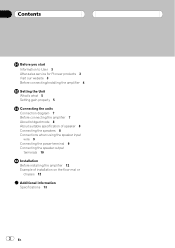
... User 3 After-sales service for Pioneer products 3 Visit our website 3 Before connecting/installing the amplifier 4 Setting the Unit What's what 5 Setting gain properly 5 Connecting the units Connection diagram 7 Before connecting the amplifier 7 About bridged mode 8 About suitable specification of speaker 8 Connecting the speakers 8 Connections when using the speaker input wire 9 Connecting the power terminal...
... User 3 After-sales service for Pioneer products 3 Visit our website 3 Before connecting/installing the amplifier 4 Setting the Unit What's what 5 Setting gain properly 5 Connecting the units Connection diagram 7 Before connecting the amplifier 7 About bridged mode 8 About suitable specification of speaker 8 Connecting the speakers 8 Connections when using the speaker input wire 9 Connecting the power terminal...
Owner's Manual
Page 4
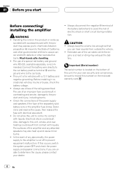
...low enough so that you start Before connecting/ installing the amplifier WARNING ! For your dealer. ! The use of California and other governmental entities to the amplifier is recommended. Always use of a special red battery and ground wire RD-223, available separately, is cut off to record this...the battery voltage. ! CAUTION ! gine is for vehicles with a 12 V battery and negative grounding. sociated with accessories sold battery wire or the amplifier fuse blows. This unit is at rest or idling may exhaust the battery. Do not allow this product or cords as- Extended use...
...low enough so that you start Before connecting/ installing the amplifier WARNING ! For your dealer. ! The use of California and other governmental entities to the amplifier is recommended. Always use of a special red battery and ground wire RD-223, available separately, is cut off to record this...the battery voltage. ! CAUTION ! gine is for vehicles with a 12 V battery and negative grounding. sociated with accessories sold battery wire or the amplifier fuse blows. This unit is at rest or idling may exhaust the battery. Do not allow this product or cords as- Extended use...
Owner's Manual
Page 7
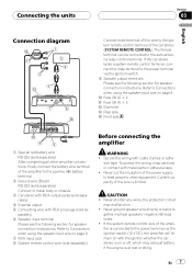
... the system remote control terminal of the power supply to feed power to other amplifier connections, finally connect the battery wire terminal of the amplifier to the positive (+) battery terminal. 2 Ground wire (Black) RD-223 (sold separately) Connect to metal body or chassis. 3 Car stereo...The female terminal can be connected to - Refer to Connections when using the speaker input wire on page 9. 7 RCA input jack 8 System remote control wire (sold separately) Before connecting the amplifier WARNING ! Never cut the insulation of the car stereo (SYSTEM REMOTE CONTROL). gether ...
... the system remote control terminal of the power supply to feed power to other amplifier connections, finally connect the battery wire terminal of the amplifier to the positive (+) battery terminal. 2 Ground wire (Black) RD-223 (sold separately) Connect to metal body or chassis. 3 Car stereo...The female terminal can be connected to - Refer to Connections when using the speaker input wire on page 9. 7 RCA input jack 8 System remote control wire (sold separately) Before connecting the amplifier WARNING ! Never cut the insulation of the car stereo (SYSTEM REMOTE CONTROL). gether ...
Owner's Manual
Page 8
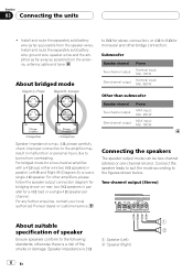
..., contact your local authorized Pioneer dealer or customer service. Speaker impedance is max. 4 W, please carefully check. For other bridge connection. Improper connection to the amplifier may result in parallel, Left + and Right * (Diagram A) or use a single 4 W speaker. Install and route the separately sold battery wire, ground wire, speaker wires and the amplifier as far away as...
..., contact your local authorized Pioneer dealer or customer service. Speaker impedance is max. 4 W, please carefully check. For other bridge connection. Improper connection to the amplifier may result in parallel, Left + and Right * (Diagram A) or use a single 4 W speaker. Install and route the separately sold battery wire, ground wire, speaker wires and the amplifier as far away as...
Owner's Manual
Page 9
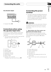
... the car body. 1 Speaker (Mono) Connections when using the speaker input wire Connect the car stereo speaker output wires to the terminal using the supplied speaker input wire. ! After completing all other amplifier connections, finally connect the battery wire terminal of this unit. 1 Positive (+) terminal 2 Engine compartment 3 Vehicle interior 4 Fuse (30 A) × 2 5 Insert the O-ring...
... the car body. 1 Speaker (Mono) Connections when using the speaker input wire Connect the car stereo speaker output wires to the terminal using the supplied speaker input wire. ! After completing all other amplifier connections, finally connect the battery wire terminal of this unit. 1 Positive (+) terminal 2 Engine compartment 3 Vehicle interior 4 Fuse (30 A) × 2 5 Insert the O-ring...
Owner's Manual
Page 10
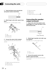
Twist 1 Lug 2 Battery wire 3 Ground wire 4 Connect the wires to wire ends. Fix the speaker wires securely with the terminal screws. 2 Attach lugs to speaker wire ends. Twist 4 Terminal screws 5 Battery wire 6 Ground wire 7 System remote control wire 3 Attach lugs to the terminal. Section 03 Connecting the units 2 Twist the battery wire, ground wire and system remote control wire. Connecting the speaker output...
Twist 1 Lug 2 Battery wire 3 Ground wire 4 Connect the wires to wire ends. Fix the speaker wires securely with the terminal screws. 2 Attach lugs to speaker wire ends. Twist 4 Terminal screws 5 Battery wire 6 Ground wire 7 System remote control wire 3 Attach lugs to the terminal. Section 03 Connecting the units 2 Twist the battery wire, ground wire and system remote control wire. Connecting the speaker output...
Owner's Manual
Page 11
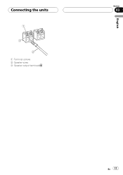
Connecting the units 1 Terminal screws 2 Speaker wires 3 Speaker output terminals English Section 03 En 11
Connecting the units 1 Terminal screws 2 Speaker wires 3 Speaker output terminals English Section 03 En 11
Owner's Manual
Page 12
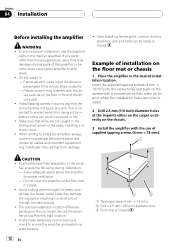
...insulation, resulting in a short-circuit through hot areas, such as on the floor mat or chassis 1 Place the amplifier in : - Make sure that wires are behind the panel and protect all cables and important equipment (e.g. Insert the supplied tapping screws (4 mm × .... fier, ensure the following during installation: - Avoid routing wires through the vehicle body. ! Section 04 Installation Before installing the amplifier WARNING ! If any wire. Install tapping screws in fire. ! Do not cover the amplifier with the use the supplied parts in front of supplied tapping...
...insulation, resulting in a short-circuit through hot areas, such as on the floor mat or chassis 1 Place the amplifier in : - Make sure that wires are behind the panel and protect all cables and important equipment (e.g. Insert the supplied tapping screws (4 mm × .... fier, ensure the following during installation: - Avoid routing wires through the vehicle body. ! Section 04 Installation Before installing the amplifier WARNING ! If any wire. Install tapping screws in fire. ! Do not cover the amplifier with the use the supplied parts in front of supplied tapping...
Owner's Manual
Page 13
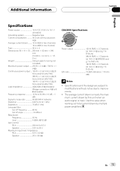
... when an audio signal is nearly the maximum current drawn by this value when working out total current drawn by multiple power amplifiers. The average current drawn is input. Specifications and the design are subject to modifications without notice due to 26 V Maximum ... × 2 Dimensions (W × H × D) ... 265 mm × 62 mm × 346 mm (10-3/8 in. ×2-1/2 in. × 1 ft. 2 in.) Weight 3.8 kg (Leads for wiring not included) Maximum power output ....... 250 W × 2 (4 W) / 760 W × 1 (4 W) Continuous power output ... 125 W × 2 (at 14.4 V, 4 W, 20 Hz to 20 kHz ...
... when an audio signal is nearly the maximum current drawn by this value when working out total current drawn by multiple power amplifiers. The average current drawn is input. Specifications and the design are subject to modifications without notice due to 26 V Maximum ... × 2 Dimensions (W × H × D) ... 265 mm × 62 mm × 346 mm (10-3/8 in. ×2-1/2 in. × 1 ft. 2 in.) Weight 3.8 kg (Leads for wiring not included) Maximum power output ....... 250 W × 2 (4 W) / 760 W × 1 (4 W) Continuous power output ... 125 W × 2 (at 14.4 V, 4 W, 20 Hz to 20 kHz ...


