Service Manual
Page 1
... 4-1, Meguro 1-Chome, Meguro-ku, Tokyo 153-8654, Japan PIONEER ELECTRONICS SERVICE INC. PIONEER ELECTRONIC [EUROPE] N.V. EXPLODED VIEWS AND PARTS LIST 2 3. PCB CONNECTION DIAGRAM 14 5. ELECTRICAL PARTS LIST 19 6. MAR. 1998 Printed in Japan SCHEMATIC DIAGRAM 8 4. SAFETY INFORMATION 2 2. CRT2191 BRIDGEABL FOUR-CHANNEL POWER AMPLIFIER GM-X1024 X1R/UC GM-X924 X1R/UC,EW,ES CONTENTS 1. Haven 1087 Keetberglaan...
... 4-1, Meguro 1-Chome, Meguro-ku, Tokyo 153-8654, Japan PIONEER ELECTRONICS SERVICE INC. PIONEER ELECTRONIC [EUROPE] N.V. EXPLODED VIEWS AND PARTS LIST 2 3. PCB CONNECTION DIAGRAM 14 5. ELECTRICAL PARTS LIST 19 6. MAR. 1998 Printed in Japan SCHEMATIC DIAGRAM 8 4. SAFETY INFORMATION 2 2. CRT2191 BRIDGEABL FOUR-CHANNEL POWER AMPLIFIER GM-X1024 X1R/UC GM-X924 X1R/UC,EW,ES CONTENTS 1. Haven 1087 Keetberglaan...
Service Manual
Page 8
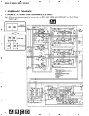
... PAGE) Note: When ordering service parts, be sure to refer to "EXPLODED VIEWS AND PARTS LIST" or "ELECTRICAL PARTS LIST". 1 2 3 4 GM-X1024,GM-X924 3. A-a Large size A-a A-b SCH diagram B -10dBm -7.7dBm -10.2dBm HPF LPF VR501:FREQUENCY S501:LPF/HPF OFF -14.4dB A-a A-b Guide page B A-a A-b Detailed page 2CH/4CH 2CH 4CH ISOLATOR C HPF VR501:... REGULATOR D 8 ABCD 1 2 3 VR551:FREQUENCY OFF S551:LPF/HPF SWITCHING CONTROL 3.9V 3.9V 14.4V 5V 5V 2.4V 2.4V 14.4V 0V 3.8V 1.8V 2.2V 0V GM-X924/X1R/EW, GM-X924/X1R/ES BFC H L 6.5V D903,D904:NSPWF50S(AQ) 4
... PAGE) Note: When ordering service parts, be sure to refer to "EXPLODED VIEWS AND PARTS LIST" or "ELECTRICAL PARTS LIST". 1 2 3 4 GM-X1024,GM-X924 3. A-a Large size A-a A-b SCH diagram B -10dBm -7.7dBm -10.2dBm HPF LPF VR501:FREQUENCY S501:LPF/HPF OFF -14.4dB A-a A-b Guide page B A-a A-b Detailed page 2CH/4CH 2CH 4CH ISOLATOR C HPF VR501:... REGULATOR D 8 ABCD 1 2 3 VR551:FREQUENCY OFF S551:LPF/HPF SWITCHING CONTROL 3.9V 3.9V 14.4V 5V 5V 2.4V 2.4V 14.4V 0V 3.8V 1.8V 2.2V 0V GM-X924/X1R/EW, GM-X924/X1R/ES BFC H L 6.5V D903,D904:NSPWF50S(AQ) 4
Service Manual
Page 14
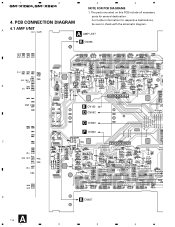
A 4.1 AMP UNIT A AMP UNIT B CN856 B C D A 14 1 OUTPUT INPUT 2CH/4CH B E CN102 D CN552 C CN502 F CN302 B CN857 2 3 A 4 The parts mounted on this PCB include all necessary parts for respective destinations, be sure to check with the schematic diagram. PCB CONNECTION DIAGRAM For further information for several destination. 4. 1 2 GM-X1024,GM-X924 3 4 NOTE FOR PCB DIAGRAMS 1.
A 4.1 AMP UNIT A AMP UNIT B CN856 B C D A 14 1 OUTPUT INPUT 2CH/4CH B E CN102 D CN552 C CN502 F CN302 B CN857 2 3 A 4 The parts mounted on this PCB include all necessary parts for respective destinations, be sure to check with the schematic diagram. PCB CONNECTION DIAGRAM For further information for several destination. 4. 1 2 GM-X1024,GM-X924 3 4 NOTE FOR PCB DIAGRAMS 1.
Service Manual
Page 25
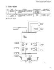
...) VR301(B Lch) VR401(B Rch) VR951 VR952 Specifications mV Meter(1) : 20±6mV mV Meter(2) : +29±3V mV Meter(3) : -29±3V - ADJUSTMENT No. Connection Diagram +14.4V DC Regulated Power Supply 4Ω (2W) SPEAKER A OUTPUT 4Ω (2W) 4Ω (2W) SPEAKER B OUTPUT 4Ω (2W) POWER GND SYSTEM CONTROL VR951 VR952 mV... GND 1kΩ VR401 E E VR301 E E Q415 Q416 mV Meter (1) Q315 Q316 mV Meter (1) AR 1kΩ 1kΩ 1kΩ BL AL Fig. 12 25 GM-X1024,GM-X924 6. Item Conditions 1 Idling current Input ;
...) VR301(B Lch) VR401(B Rch) VR951 VR952 Specifications mV Meter(1) : 20±6mV mV Meter(2) : +29±3V mV Meter(3) : -29±3V - ADJUSTMENT No. Connection Diagram +14.4V DC Regulated Power Supply 4Ω (2W) SPEAKER A OUTPUT 4Ω (2W) 4Ω (2W) SPEAKER B OUTPUT 4Ω (2W) POWER GND SYSTEM CONTROL VR951 VR952 mV... GND 1kΩ VR401 E E VR301 E E Q415 Q416 mV Meter (1) Q315 Q316 mV Meter (1) AR 1kΩ 1kΩ 1kΩ BL AL Fig. 12 25 GM-X1024,GM-X924 6. Item Conditions 1 Idling current Input ;
Service Manual
Page 30
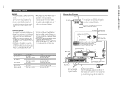
...female terminal can be exceeded, causing overheating. Otherwise damage will not interfere with a 12-volt battery and negative grounding. input: Min. 300 W Connection Diagram Fuse (30 A) Grommet Fuse (30 A) Special red battery wire [RD-223] (sold separately). If the car stereo does not have a system ... power terminal through the ignition switch. Turn the car stereo off . input: Min. 130 W Nominal input: Min. 150 W Max. GM-X1024,GM-X924 30 Connecting the Unit CAUTION • Disconnect the negative (-) terminal of the battery to avoid the risk of short-circuit and damage to...
...female terminal can be exceeded, causing overheating. Otherwise damage will not interfere with a 12-volt battery and negative grounding. input: Min. 300 W Connection Diagram Fuse (30 A) Grommet Fuse (30 A) Special red battery wire [RD-223] (sold separately). If the car stereo does not have a system ... power terminal through the ignition switch. Turn the car stereo off . input: Min. 130 W Nominal input: Min. 150 W Max. GM-X1024,GM-X924 30 Connecting the Unit CAUTION • Disconnect the negative (-) terminal of the battery to avoid the risk of short-circuit and damage to...
Service Manual
Page 32
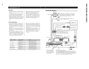
...jack RCA input jack A, B Fuse (30 A) × 2 Connecting wires with the standards listed below. Blue [RD-223] (sold separately). GM-X1024,GM-X924 32 Connecting the Unit CAUTION • Disconnect the negative (-) terminal of the battery to avoid the risk of short-circuit and damage to the ...not interfere with cable clamps or adhesive tape. Install and route the separately sold separately). Connect to the speaker. input: Min. 300 W Connection Diagram Fuse (30 A) Grommet Fuse (30 A) Special red battery wire [RD-223] (sold battery wire and ground wire, speaker wires, and the...
...jack RCA input jack A, B Fuse (30 A) × 2 Connecting wires with the standards listed below. Blue [RD-223] (sold separately). GM-X1024,GM-X924 32 Connecting the Unit CAUTION • Disconnect the negative (-) terminal of the battery to avoid the risk of short-circuit and damage to the ...not interfere with cable clamps or adhesive tape. Install and route the separately sold separately). Connect to the speaker. input: Min. 300 W Connection Diagram Fuse (30 A) Grommet Fuse (30 A) Special red battery wire [RD-223] (sold battery wire and ground wire, speaker wires, and the...

