Service Manual
Page 1
.../X1R/UC Service Manual ORDER NO. OPERATIONS AND SPECIFICATIONS 29 PIONEER ELECTRONIC CORPORATION 4-1, Meguro 1-Chome, Meguro-ku, Tokyo 153-8654, Japan PIONEER ELECTRONICS SERVICE INC. SCHEMATIC DIAGRAM 8 4. Haven 1087 Keetberglaan 1, 9120 Melsele, Belgium PIONEER ELECTRONICS ASIACENTRE PTE.LTD. 501 Orchard Road, #10-00, Lane Wheelock Place, Singapore 23880 C PIONEER ELECTRONIC CORPORATION 1998 K-FED. CRT2191 BRIDGEABL FOUR-CHANNEL POWER AMPLIFIER GM-X1024 X1R/UC GM-X924 X1R/UC...
.../X1R/UC Service Manual ORDER NO. OPERATIONS AND SPECIFICATIONS 29 PIONEER ELECTRONIC CORPORATION 4-1, Meguro 1-Chome, Meguro-ku, Tokyo 153-8654, Japan PIONEER ELECTRONICS SERVICE INC. SCHEMATIC DIAGRAM 8 4. Haven 1087 Keetberglaan 1, 9120 Melsele, Belgium PIONEER ELECTRONICS ASIACENTRE PTE.LTD. 501 Orchard Road, #10-00, Lane Wheelock Place, Singapore 23880 C PIONEER ELECTRONIC CORPORATION 1998 K-FED. CRT2191 BRIDGEABL FOUR-CHANNEL POWER AMPLIFIER GM-X1024 X1R/UC GM-X924 X1R/UC...
Service Manual
Page 2
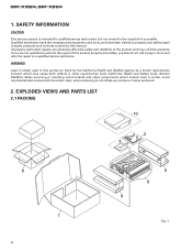
SAFETY INFORMATION CAUTION This service manual is not meant for qualified service technicians; Improperly performed repairs can adversely affect the safety and reliability of this manual. EXPLODED VIEWS AND PARTS LIST 2.1 PACKING 10 35 2 4 8 7 2 9 6 9 Fig. 1 GM-X1024,GM-X924 1. Also, when soldering do so and refer the repair to perform the repair of the product and may cause birth defects or other components...
SAFETY INFORMATION CAUTION This service manual is not meant for qualified service technicians; Improperly performed repairs can adversely affect the safety and reliability of this manual. EXPLODED VIEWS AND PARTS LIST 2.1 PACKING 10 35 2 4 8 7 2 9 6 9 Fig. 1 GM-X1024,GM-X924 1. Also, when soldering do so and refer the repair to perform the repair of the product and may cause birth defects or other components...
Service Manual
Page 3
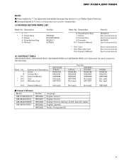
... used HRD0068 - Screws adjacent to ∇ mark on the product are constructed the same except for disassembly. (1) PACKING SECTION PARTS LIST Mark No. HRD0056 HRD0057 HRD0059 HRD0058 HRD0068 Language English, French English, French English, French, German, Dutch, Spanish, Italian English, Spanish Arabic, Poltuguese (B) 3 HEA0044 BYC40P180FZK HEG0011 HLP0001 Mark No. Owner's Manual Model GM-X1024/X1R/UC GM-X924/X1R/UC GM-X924...
... used HRD0068 - Screws adjacent to ∇ mark on the product are constructed the same except for disassembly. (1) PACKING SECTION PARTS LIST Mark No. HRD0056 HRD0057 HRD0059 HRD0058 HRD0068 Language English, French English, French English, French, German, Dutch, Spanish, Italian English, Spanish Arabic, Poltuguese (B) 3 HEA0044 BYC40P180FZK HEG0011 HLP0001 Mark No. Owner's Manual Model GM-X1024/X1R/UC GM-X924/X1R/UC GM-X924...
Service Manual
Page 5
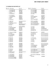
...Lighting Conductor 14 Amp Unit 15 Screw See Contrast table (2) HNS0053 HNV0012 See Contrast table (2) BMS30P060FZK 16 Screw 17 Terminal(CN905) 18 Plug(CN503) 19 Plug(CN553) 20 Connector(CN853) BMS30P080FMC CKF1059 CKS1039 CKS1039 CKS3813 21 Connector(CN852) 22 Holder 23 Cord(CN104) 24 Cord(CN304) 25 Bass Bar CKS3814 CNV4017 HDE5500 HDE5500 HNC0043 26 Bass Bar 27 Bass Bar 28 Bass Bar 29 Bass...84 Transistor(Q116,216,316,416) 2SA1919 85 Thermistor(TH901) CCX1027 86 Thermistor(TH902,903) 87-93 94 Sheet CCX1035 CNM5950 5 GM-X1024,GM-X924 (1) EXTERIOR SECTION PARTS LIST Mark No.
...Lighting Conductor 14 Amp Unit 15 Screw See Contrast table (2) HNS0053 HNV0012 See Contrast table (2) BMS30P060FZK 16 Screw 17 Terminal(CN905) 18 Plug(CN503) 19 Plug(CN553) 20 Connector(CN853) BMS30P080FMC CKF1059 CKS1039 CKS1039 CKS3813 21 Connector(CN852) 22 Holder 23 Cord(CN104) 24 Cord(CN304) 25 Bass Bar CKS3814 CNV4017 HDE5500 HDE5500 HNC0043 26 Bass Bar 27 Bass Bar 28 Bass Bar 29 Bass...84 Transistor(Q116,216,316,416) 2SA1919 85 Thermistor(TH901) CCX1027 86 Thermistor(TH902,903) 87-93 94 Sheet CCX1035 CNM5950 5 GM-X1024,GM-X924 (1) EXTERIOR SECTION PARTS LIST Mark No.
Service Manual
Page 6
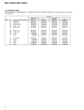
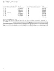
GM-X1024,GM-X924 (2) CONTRAST TABLE GM-X1024/X1R/UC, GM-X924/X1R/UC, GM-X924/X1R/EW and GM-X924/X1R/ES are constructed the same except for the following: Mark No. 11 14 39 64 65 Symbol and Description Heat Sink Amp Unit Network Unit Plate Unit Sheet Unit GM-X1024 X1R/UC HNR0073 HWH0066 HWG0008 HXA0262 HXA0264 Part No. GM-X924 X1R/UC X1R/EW HNR0093 HNR0093...
GM-X1024,GM-X924 (2) CONTRAST TABLE GM-X1024/X1R/UC, GM-X924/X1R/UC, GM-X924/X1R/EW and GM-X924/X1R/ES are constructed the same except for the following: Mark No. 11 14 39 64 65 Symbol and Description Heat Sink Amp Unit Network Unit Plate Unit Sheet Unit GM-X1024 X1R/UC HNR0073 HWH0066 HWG0008 HXA0262 HXA0264 Part No. GM-X924 X1R/UC X1R/EW HNR0093 HNR0093...
Service Manual
Page 8
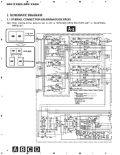
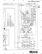
... DC-AC INVERTER -15V REGULATOR D 8 ABCD 1 2 3 VR551:FREQUENCY OFF S551:LPF/HPF SWITCHING CONTROL 3.9V 3.9V 14.4V 5V 5V 2.4V 2.4V 14.4V 0V 3.8V 1.8V 2.2V 0V GM-X924/X1R/EW, GM-X924/X1R/ES BFC H L 6.5V D903,D904:NSPWF50S(AQ) 4 SCHEMATIC DIAGRAM A 3.1 OVERALL CONNECTION DIAGRAM(GUIDE PAGE) Note: When ordering service parts, be sure to refer to "EXPLODED VIEWS AND PARTS LIST" or "ELECTRICAL PARTS LIST".
... DC-AC INVERTER -15V REGULATOR D 8 ABCD 1 2 3 VR551:FREQUENCY OFF S551:LPF/HPF SWITCHING CONTROL 3.9V 3.9V 14.4V 5V 5V 2.4V 2.4V 14.4V 0V 3.8V 1.8V 2.2V 0V GM-X924/X1R/EW, GM-X924/X1R/ES BFC H L 6.5V D903,D904:NSPWF50S(AQ) 4 SCHEMATIC DIAGRAM A 3.1 OVERALL CONNECTION DIAGRAM(GUIDE PAGE) Note: When ordering service parts, be sure to refer to "EXPLODED VIEWS AND PARTS LIST" or "ELECTRICAL PARTS LIST".
Service Manual
Page 9
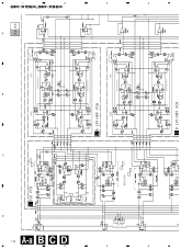
5 6 7 8 GM-X1024,GM-X924 A A-b POWER STAGE A OVER CURRENT DETECTOR B 20.4dBm E F C THERMO DETECTOR / PROTECTOR OVER VOLTAGE DETECTOR / PROTECTOR MUTE CONTROL REGULATOR CONTROL 0.1V 3.2V 0.3V 5V 0V 0.2V 0V 0V 0.2V 14.4V 14.2V 10.7V 14.4V 14.4V 5 6 D Fig. 3 AEF 9 7 8
5 6 7 8 GM-X1024,GM-X924 A A-b POWER STAGE A OVER CURRENT DETECTOR B 20.4dBm E F C THERMO DETECTOR / PROTECTOR OVER VOLTAGE DETECTOR / PROTECTOR MUTE CONTROL REGULATOR CONTROL 0.1V 3.2V 0.3V 5V 0V 0.2V 0V 0V 0.2V 14.4V 14.2V 10.7V 14.4V 14.4V 5 6 D Fig. 3 AEF 9 7 8
Service Manual
Page 10
A B C D 1 GM-X1024,GM-X924 10 A-a B C D 1 -10dBm -7.7dBm -10.2dBm HPF LPF VR501:FREQUENCY S501:LPF/HPF OFF A-a A-b -14.4dBm 2 2 3 3 2CH/4CH 2CH 4CH ISOLATOR HPF VR501:FREQUENCY OFF S501:LPF/HPF LPF VR551:FREQUENCY S551:LPF/HPF OFF VR551:FREQUENCY OFF S551:LPF/HPF 4 4
A B C D 1 GM-X1024,GM-X924 10 A-a B C D 1 -10dBm -7.7dBm -10.2dBm HPF LPF VR501:FREQUENCY S501:LPF/HPF OFF A-a A-b -14.4dBm 2 2 3 3 2CH/4CH 2CH 4CH ISOLATOR HPF VR501:FREQUENCY OFF S501:LPF/HPF LPF VR551:FREQUENCY S551:LPF/HPF OFF VR551:FREQUENCY OFF S551:LPF/HPF 4 4
Service Manual
Page 11
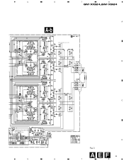
OFF S551:LPF/HPF 5 5 6 6 -15.4V +15.4V +15V REGULATOR -42.1V +42.1V -29.0V +29.0V RECTIFICATION DC-AC INVERTER -15V REGULATOR SWITCHING CONTROL 3.9V 3.9V 14.4V 5V 5V 2.4V 2.4V 14.4V 0V 3.8V 1.8V 2.2V 0V GM-X924/X1R/EW, GM-X924/X1R/ES BFC H L 6.5V D903,D904:NSPWF50S(AQ) A-a A-b 7 7 GM-X1024,GM-X924 A-a B D 11 8 8 Fig. 4 A B C D
OFF S551:LPF/HPF 5 5 6 6 -15.4V +15.4V +15V REGULATOR -42.1V +42.1V -29.0V +29.0V RECTIFICATION DC-AC INVERTER -15V REGULATOR SWITCHING CONTROL 3.9V 3.9V 14.4V 5V 5V 2.4V 2.4V 14.4V 0V 3.8V 1.8V 2.2V 0V GM-X924/X1R/EW, GM-X924/X1R/ES BFC H L 6.5V D903,D904:NSPWF50S(AQ) A-a A-b 7 7 GM-X1024,GM-X924 A-a B D 11 8 8 Fig. 4 A B C D
Service Manual
Page 14
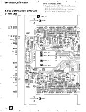
A 4.1 AMP UNIT A AMP UNIT B CN856 B C D A 14 1 OUTPUT INPUT 2CH/4CH B E CN102 D CN552 C CN502 F CN302 B CN857 2 3 A 4 The parts mounted on this PCB include all necessary parts for respective destinations, be sure to check with the schematic diagram. PCB CONNECTION DIAGRAM For further information for several destination. 4. 1 2 GM-X1024,GM-X924 3 4 NOTE FOR PCB DIAGRAMS 1.
A 4.1 AMP UNIT A AMP UNIT B CN856 B C D A 14 1 OUTPUT INPUT 2CH/4CH B E CN102 D CN552 C CN502 F CN302 B CN857 2 3 A 4 The parts mounted on this PCB include all necessary parts for respective destinations, be sure to check with the schematic diagram. PCB CONNECTION DIAGRAM For further information for several destination. 4. 1 2 GM-X1024,GM-X924 3 4 NOTE FOR PCB DIAGRAMS 1.
Service Manual
Page 19
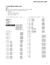
.../__S___J Chip Capacitor (except for CQS.....) CKS....., CCS....., CSZS..... =====Circuit Symbol and No.===Part Name Part No Network Unit Consists of ISO PCB A LPF/HPF PCB B LPF/HPF PCB A P.A.PCB B P.A.PCB B C D E F Unit Number : HWG0008 (GM-X1024/X1R/UC) Unit Number : HWG0009 (GM-X924/X1R/UC) Unit Number : HWG0006 (GM-X924/X1R/EW) Unit Number : HWG0007 (GM-X924/X1R/ES) Unit Name : Network Unit MISCELLANEOUS IC 501 IC IC 502 IC IC 503 IC...
.../__S___J Chip Capacitor (except for CQS.....) CKS....., CCS....., CSZS..... =====Circuit Symbol and No.===Part Name Part No Network Unit Consists of ISO PCB A LPF/HPF PCB B LPF/HPF PCB A P.A.PCB B P.A.PCB B C D E F Unit Number : HWG0008 (GM-X1024/X1R/UC) Unit Number : HWG0009 (GM-X924/X1R/UC) Unit Number : HWG0006 (GM-X924/X1R/EW) Unit Number : HWG0007 (GM-X924/X1R/ES) Unit Name : Network Unit MISCELLANEOUS IC 501 IC IC 502 IC IC 503 IC...
Service Manual
Page 24
Symbol and Description GM-X1024/X1R/UC GM-X924/X1R/UC GM-X924/X1R/EW GM-X924/X1R/ES S901 Switch Not used Not used HSH-156 HSH-156 R955 Not used Not used RD1/4PU105J RD1/4PU105J 24 GM-X1024,GM-X924 =====Circuit Symbol and No.===Part Name C 957 C 959 C 960 C 961 C 962 C 963 4700µF/16V C 964 C 965 C 966 C 967 Part No CFTLA474J50 CFTLA104J50 CFTLA104J50 CQMA472J50 CQMA472J50...
Symbol and Description GM-X1024/X1R/UC GM-X924/X1R/UC GM-X924/X1R/EW GM-X924/X1R/ES S901 Switch Not used Not used HSH-156 HSH-156 R955 Not used Not used RD1/4PU105J RD1/4PU105J 24 GM-X1024,GM-X924 =====Circuit Symbol and No.===Part Name C 957 C 959 C 960 C 961 C 962 C 963 4700µF/16V C 964 C 965 C 966 C 967 Part No CFTLA474J50 CFTLA104J50 CFTLA104J50 CQMA472J50 CQMA472J50...
Service Manual
Page 25
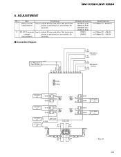
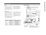
Item Conditions 1 Idling current Input ; adjust 30 seconds after 1kΩ terminate (adjustment) power is switched on , and within 20 (adjustment) seconds. Connection Diagram +14.4V DC Regulated Power Supply 4Ω (2W) SPEAKER A OUTPUT 4Ω (2W) 4Ω (2W) SPEAKER B OUTPUT 4Ω (2W) POWER GND SYSTEM CONTROL VR951 VR952 mV Meter (1) Q215 Q216 E C VR201 E mV Meter (1) Q115 Q116 E C VR101 E C mV Meter + (3) mV Meter + (2) AMP UNIT GND BR GND 1kΩ...
Item Conditions 1 Idling current Input ; adjust 30 seconds after 1kΩ terminate (adjustment) power is switched on , and within 20 (adjustment) seconds. Connection Diagram +14.4V DC Regulated Power Supply 4Ω (2W) SPEAKER A OUTPUT 4Ω (2W) 4Ω (2W) SPEAKER B OUTPUT 4Ω (2W) POWER GND SYSTEM CONTROL VR951 VR952 mV Meter (1) Q215 Q216 E C VR201 E mV Meter (1) Q115 Q116 E C VR101 E C mV Meter + (3) mV Meter + (2) AMP UNIT GND BR GND 1kΩ...
Service Manual
Page 26
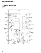
GM-X1024,GM-X924 7. GENERAL INFORMATION 7.1 IC PA2027A VCC 1 Transient voltage detector Stby 2 Bandgap DET1 3 DET2 4 + - Oneshot (1µsec) SQ R 20µA + zz 2V 2V - + 12 Filter 11 Vs_out 10 TC 9 Mute_out 26 Circuit motion:on zz 50µA zz+- 16 IN1 2V zz+- 15 IN2 2V zz+- 14 IN3 2V 13 Cont_V DET_R 5 GND 6 NC 7 NC 8 - + 4.7kΩ Bandgap:on Switch:on zz + - 2V 5.6V 0.13V + -
GM-X1024,GM-X924 7. GENERAL INFORMATION 7.1 IC PA2027A VCC 1 Transient voltage detector Stby 2 Bandgap DET1 3 DET2 4 + - Oneshot (1µsec) SQ R 20µA + zz 2V 2V - + 12 Filter 11 Vs_out 10 TC 9 Mute_out 26 Circuit motion:on zz 50µA zz+- 16 IN1 2V zz+- 15 IN2 2V zz+- 14 IN3 2V 13 Cont_V DET_R 5 GND 6 NC 7 NC 8 - + 4.7kΩ Bandgap:on Switch:on zz + - 2V 5.6V 0.13V + -
Service Manual
Page 27
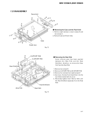
... and the Heat Sink(Sub). Remove four screws E and eight screws F. 4. GM-X1024,GM-X924 7.2 DISASSEMBLY A Panel Unit A A BB BB A B C B A A A BC Panel Unit A Case Fig. 13 - of screw E and insert them little by little until the Heat Sink(Sub) separates from the Heat Sink. 1. Remove Case and Panel Units. therefore, to remove the Amp Unit from the Heat Sink. 27 Use 2 pcs. Alternately tighten...
... and the Heat Sink(Sub). Remove four screws E and eight screws F. 4. GM-X1024,GM-X924 7.2 DISASSEMBLY A Panel Unit A A BB BB A B C B A A A BC Panel Unit A Case Fig. 13 - of screw E and insert them little by little until the Heat Sink(Sub) separates from the Heat Sink. 1. Remove Case and Panel Units. therefore, to remove the Amp Unit from the Heat Sink. 27 Use 2 pcs. Alternately tighten...
Service Manual
Page 29
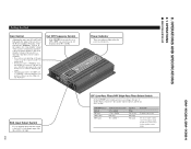
... Setting the Unit Gain Control Adjusting the gain controls A and B will help match the output of speaker that is set the gain controls for the speakers you are using. 29 If the sound level is too low or distorts, adjust the gain control. • Adjust the gain control to the right. GM-X1024,GM-X924 RCA Input Select Switch For two-channel input, slide this switch to the "MIN" side of the car stereo is turned up , turn these controls counterclockwise. • If you only use one input plug, set to LPF...
... Setting the Unit Gain Control Adjusting the gain controls A and B will help match the output of speaker that is set the gain controls for the speakers you are using. 29 If the sound level is too low or distorts, adjust the gain control. • Adjust the gain control to the right. GM-X1024,GM-X924 RCA Input Select Switch For two-channel input, slide this switch to the "MIN" side of the car stereo is turned up , turn these controls counterclockwise. • If you only use one input plug, set to LPF...
Service Manual
Page 30
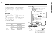
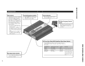
... side RCA output jack RCA input jack A, B Fuse (30 A) × 2 Speaker output terminal See the "Connecting the Speaker wires" section for vehicles with RCA pin plugs (sold separately). input: Min. 300 W Connection Diagram Fuse (30 A) Grommet Fuse (30 A) Special red battery wire [RD-223] (sold separately). Connecting wires with a 12-volt battery and negative grounding. Turn the car stereo off . After making all other equipment by cutting the insulation of the power supply wire to the positive (+) terminal of the battery. GM-X1024,GM-X924 30 Connecting the Unit...
... side RCA output jack RCA input jack A, B Fuse (30 A) × 2 Speaker output terminal See the "Connecting the Speaker wires" section for vehicles with RCA pin plugs (sold separately). input: Min. 300 W Connection Diagram Fuse (30 A) Grommet Fuse (30 A) Special red battery wire [RD-223] (sold separately). Connecting wires with a 12-volt battery and negative grounding. Turn the car stereo off . After making all other equipment by cutting the insulation of the power supply wire to the positive (+) terminal of the battery. GM-X1024,GM-X924 30 Connecting the Unit...
Service Manual
Page 31
GM-X924/X1R/EW Setting the Unit Gain Control Adjusting the gain controls A and B will help match the output of the car stereo to 120 Hz - If the sound level is too low or distorts, adjust the gain control. • Adjust the gain control to the "MIN" side of the car stereo is connected to 120 Hz. Power Indicator The power indicator lights when the power is connected to the speaker output connector and the car stereo system: LPF/HPF Select Switch LPF (Left) OFF (Center) HPF (Right) Audio frequency range to...
GM-X924/X1R/EW Setting the Unit Gain Control Adjusting the gain controls A and B will help match the output of the car stereo to 120 Hz - If the sound level is too low or distorts, adjust the gain control. • Adjust the gain control to the "MIN" side of the car stereo is connected to 120 Hz. Power Indicator The power indicator lights when the power is connected to the speaker output connector and the car stereo system: LPF/HPF Select Switch LPF (Left) OFF (Center) HPF (Right) Audio frequency range to...
Service Manual
Page 32
... car stereo is used, do not connect anything to RCA input jack B. Install and route the separately sold battery wire and ground wire, speaker wires, and the amplifier as far away as possible from the speaker wires. input: Min. 130 W Nominal input: Min. 150 W Max. Car stereo with RCA output jacks Reverse side RCA output jack RCA input jack A, B Fuse (30 A) × 2 Connecting wires with RCA pin plugs (sold separately). The female terminal can be 1 to 8 ohms. (2 to 8 Ω for stereo, monaural and other bridge connections.) Speaker Channel Four-channel...
... car stereo is used, do not connect anything to RCA input jack B. Install and route the separately sold battery wire and ground wire, speaker wires, and the amplifier as far away as possible from the speaker wires. input: Min. 130 W Nominal input: Min. 150 W Max. Car stereo with RCA output jacks Reverse side RCA output jack RCA input jack A, B Fuse (30 A) × 2 Connecting wires with RCA pin plugs (sold separately). The female terminal can be 1 to 8 ohms. (2 to 8 Ω for stereo, monaural and other bridge connections.) Speaker Channel Four-channel...
Service Manual
Page 33
... maximum current drawn by this unit when an audio signal is input. GM-X1024,GM-X924 33 GM-X924/X1R/UC, GM-X924/X1R/EW, GM-X924/X1R/ES Specifications Power source ...14.4 V DC (10.8 - 15.1 V allowable) Grounding system ...Negative type Current consumption ...39 A (at continuous power, 4 Ω) Average current drawn* ...11 A (4 Ω for four channels) 18 A (4 Ω for two channels) Fuse ...30 A × 2 Dimensions ...255 (W) × 61 (H) × 310...
... maximum current drawn by this unit when an audio signal is input. GM-X1024,GM-X924 33 GM-X924/X1R/UC, GM-X924/X1R/EW, GM-X924/X1R/ES Specifications Power source ...14.4 V DC (10.8 - 15.1 V allowable) Grounding system ...Negative type Current consumption ...39 A (at continuous power, 4 Ω) Average current drawn* ...11 A (4 Ω for four channels) 18 A (4 Ω for two channels) Fuse ...30 A × 2 Dimensions ...255 (W) × 61 (H) × 310...


