Service Manual
Page 1
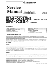
CRT2168 BRIDGEABLE FOUR-CHANNEL POWER AMPLIFIER GM-X424 X1R/UC, ES, EW GM-X324 X1R/UC CONTENTS 1. ADJUSTMENT 16 7. WARNING Lead in solder used in Japan PIONEER ELECTRONIC CORPORATION 4-1, Meguro 1-Chome, Meguro-ku, Tokyo 153-8654, Japan PIONEER ELECTRONICS SERVICE INC. Service Manual ORDER NO.... a qualified service technician. Improperly performed repairs can adversely affect the safety and reliability of this product properly and safely; PIONEER ELECTRONIC [EUROPE] N.V. you should not risk trying to perform the repair of the product and may void the warranty....
CRT2168 BRIDGEABLE FOUR-CHANNEL POWER AMPLIFIER GM-X424 X1R/UC, ES, EW GM-X324 X1R/UC CONTENTS 1. ADJUSTMENT 16 7. WARNING Lead in solder used in Japan PIONEER ELECTRONIC CORPORATION 4-1, Meguro 1-Chome, Meguro-ku, Tokyo 153-8654, Japan PIONEER ELECTRONICS SERVICE INC. Service Manual ORDER NO.... a qualified service technician. Improperly performed repairs can adversely affect the safety and reliability of this product properly and safely; PIONEER ELECTRONIC [EUROPE] N.V. you should not risk trying to perform the repair of the product and may void the warranty....
Service Manual
Page 7
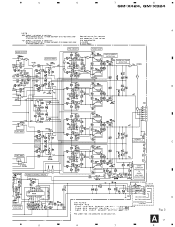
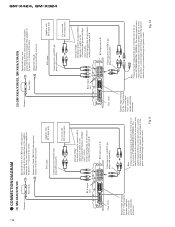
5 6 7 8 GM-X424, GM-X324 A BASS BOOST 4R7/50 BUFFER AMP PRE DRIVER POWER AMP OVER CURRENT DETECTOR OVER VOLTAGE DETECTOR 4R7/50 B FLAT AMP FLAT AMP MUTE MUTE POWER CONTROL / MUTE 22/50 R VOLTAGE TETECTOR 5 6 POWER DETECTOR C OVER CURRENT PROTECTOR & OVER VOLTAGE PROTECTOR ES and EW models only GROUND WIRE BATTERY WIRE SYSTEM REMOTE CONTROL D Fig. 3 A7 7 8
5 6 7 8 GM-X424, GM-X324 A BASS BOOST 4R7/50 BUFFER AMP PRE DRIVER POWER AMP OVER CURRENT DETECTOR OVER VOLTAGE DETECTOR 4R7/50 B FLAT AMP FLAT AMP MUTE MUTE POWER CONTROL / MUTE 22/50 R VOLTAGE TETECTOR 5 6 POWER DETECTOR C OVER CURRENT PROTECTOR & OVER VOLTAGE PROTECTOR ES and EW models only GROUND WIRE BATTERY WIRE SYSTEM REMOTE CONTROL D Fig. 3 A7 7 8
Service Manual
Page 17
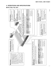
... boost level control can be output Very-low-frequency range Full range Low-frequency range to a Pioneer car stereo with RCA output jacks. OPERATIONS AND SPECIFICATIONS - If the output is low even when... selected by the bass boost frequency control to 0 to the "NORMAL" position. SETTING THE UNIT GM-X424, GM-X324 Speaker Out A: LPF (Low-Pass Filter)/HPF (High-Pass Filter) Select Switch Set the ...the type of the speaker that is set the switch to 12 dB. Power Indicator The power indicator lights when the power is too low or distorts, adjust the gain control. Normally, set ...
... boost level control can be output Very-low-frequency range Full range Low-frequency range to a Pioneer car stereo with RCA output jacks. OPERATIONS AND SPECIFICATIONS - If the output is low even when... selected by the bass boost frequency control to 0 to the "NORMAL" position. SETTING THE UNIT GM-X424, GM-X324 Speaker Out A: LPF (Low-Pass Filter)/HPF (High-Pass Filter) Select Switch Set the ...the type of the speaker that is set the switch to 12 dB. Power Indicator The power indicator lights when the power is too low or distorts, adjust the gain control. Normally, set ...
Service Manual
Page 18
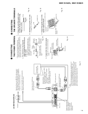
... CONTROL). Speaker output terminal See the "Connecting the Speakers and Input wires" section for speaker connection instructions. Fig. 10 GM-X424, GM-X324 18 - CONNECTION DIAGRAM (1) GM-X424/X1R/UC Grommet Fuse (30 A) Special red battery wire [RD-222] (sold separately). RCA input Connecting wires with ...) Amplifier with RCA input jacks Car stereo with RCA pin plugs (sold separately). The female terminal can be connected to the power terminal through the ignition switch. RCA input jack A, B Connecting wires with RCA output jacks RCA output jack Fuse (25A) External...
... CONTROL). Speaker output terminal See the "Connecting the Speakers and Input wires" section for speaker connection instructions. Fig. 10 GM-X424, GM-X324 18 - CONNECTION DIAGRAM (1) GM-X424/X1R/UC Grommet Fuse (30 A) Special red battery wire [RD-222] (sold separately). RCA input Connecting wires with ...) Amplifier with RCA input jacks Car stereo with RCA pin plugs (sold separately). The female terminal can be connected to the power terminal through the ignition switch. RCA input jack A, B Connecting wires with RCA output jacks RCA output jack Fuse (25A) External...
Service Manual
Page 19
...male terminal to metal body or chassis. Connect the wires to the terminal. • Fix the wires securely with the terminal screws. GM-X424, GM-X324 19 (3) GM-X324/X1R/UC Grommet Fuse (30 A) Fuse (25 A) Speaker output terminal See the "Connecting the Speakers and Input wires" section ... terminal of the amplifier to RCA input jacks A and B, see the "Connecting the Speakers and Input wires" section. Connect to the power terminal through the ignition switch. Connecting wires with RCA pin plugs (sold separately). Car stereo with the amplifier and connect directly to the ...
...male terminal to metal body or chassis. Connect the wires to the terminal. • Fix the wires securely with the terminal screws. GM-X424, GM-X324 19 (3) GM-X324/X1R/UC Grommet Fuse (30 A) Fuse (25 A) Speaker output terminal See the "Connecting the Speakers and Input wires" section ... terminal of the amplifier to RCA input jacks A and B, see the "Connecting the Speakers and Input wires" section. Connect to the power terminal through the ignition switch. Connecting wires with RCA pin plugs (sold separately). Car stereo with the amplifier and connect directly to the ...
Service Manual
Page 21
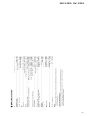
...out total current drawn by this unit when an audio signal is input. GM-X424, GM-X324 21 SPECIFICATIONS Power source ...14.4 V DC (10.8 - 15.1 V allowable) Grounding system ...Negative type Current consumption ...18 A (at continuous power, 4 Ω) Average current drawn* ...5.5 A (4 Ω for ...215; 2 (at 14.4V, 4 Ω, 20 - 20,000 Hz, 0.8% THD) 35 W × 4 (at 14.4V, 2 Ω, 20 - 20,000 Hz, 0.8% THD) Continuous power output (EW model) 40 W × 4 / 90 W × 2 (DIN45324, +B=14.4 V) Load impedance ...4 Ω (2 - 8 Ω allowable) (Bridge connection: 4 - 8 &#...
...out total current drawn by this unit when an audio signal is input. GM-X424, GM-X324 21 SPECIFICATIONS Power source ...14.4 V DC (10.8 - 15.1 V allowable) Grounding system ...Negative type Current consumption ...18 A (at continuous power, 4 Ω) Average current drawn* ...5.5 A (4 Ω for ...215; 2 (at 14.4V, 4 Ω, 20 - 20,000 Hz, 0.8% THD) 35 W × 4 (at 14.4V, 2 Ω, 20 - 20,000 Hz, 0.8% THD) Continuous power output (EW model) 40 W × 4 / 90 W × 2 (DIN45324, +B=14.4 V) Load impedance ...4 Ω (2 - 8 Ω allowable) (Bridge connection: 4 - 8 &#...

