Service Manual
Page 1
... repairs can adversely affect the safety and reliability of this product properly and safely; WARNING Lead in solder used in this product is listed by the California Health and Welfare agency as those covered by this manual. PIONEER ELECTRONIC [EUROPE] N.V. EXPLODED VIEWS AND PARTS LIST 2 3. PCB CONNECTION DIAGRAM 8 1. PIONEER ELECTRONIC CORPORATION 4-1, Meguro 1-Chome, Meguro-ku, Tokyo 153-8654, Japan PIONEER ELECTRONICS SERVICE...
... repairs can adversely affect the safety and reliability of this product properly and safely; WARNING Lead in solder used in this product is listed by the California Health and Welfare agency as those covered by this manual. PIONEER ELECTRONIC [EUROPE] N.V. EXPLODED VIEWS AND PARTS LIST 2 3. PCB CONNECTION DIAGRAM 8 1. PIONEER ELECTRONIC CORPORATION 4-1, Meguro 1-Chome, Meguro-ku, Tokyo 153-8654, Japan PIONEER ELECTRONICS SERVICE...
Service Manual
Page 2
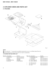
Description 6 Polyethylene Bag 7 Terminal(x8) 8 Cord Assy 9-1 Owner's Manual 9-2 Owner's Manual Part No. Screws adjacent to ∇ mark on the product are not in our Master Spare Parts List. - Description 1 Contain Box 2 Carton 3 Protector 4 Polyethylene Bag 5 Screw(x4) Part No. GM-X424, GM-X324 2. See Contrast table (2) See Contrast table (2) HHP0020 HEG0009 BYC40P180FZK Mark No. EXPLODED VIEWS AND PARTS LIST 2.1 PACKING Fig. 1 NOTE: - Parts marked by "*"are generally...
Description 6 Polyethylene Bag 7 Terminal(x8) 8 Cord Assy 9-1 Owner's Manual 9-2 Owner's Manual Part No. Screws adjacent to ∇ mark on the product are not in our Master Spare Parts List. - Description 1 Contain Box 2 Carton 3 Protector 4 Polyethylene Bag 5 Screw(x4) Part No. GM-X424, GM-X324 2. See Contrast table (2) See Contrast table (2) HHP0020 HEG0009 BYC40P180FZK Mark No. EXPLODED VIEWS AND PARTS LIST 2.1 PACKING Fig. 1 NOTE: - Parts marked by "*"are generally...
Service Manual
Page 3
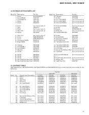
... 3 Owner's Manual Model GM-X424/X1R/UC GM-X424/X1R/ES GM-X424/X1R/EW GM-X324/X1R/UC Part No. GM-X424, GM-X324 (2) CONTRAST TABLE GM-X424/X1R/UC, GM-X424/X1R/ES, GM-X424/X1R/EW and GM-X324/X1R/UC are constructed the same except for the following: Mark No. 1 2 7 8 9-1 Symbol and Description Contain Box Carton Terminal(x8) Cord Assy Owner's Manual X1R/UC HHL0142 HHG0142 HKC0001 Not used ARY1048 - GM-X424 X1R...
... 3 Owner's Manual Model GM-X424/X1R/UC GM-X424/X1R/ES GM-X424/X1R/EW GM-X324/X1R/UC Part No. GM-X424, GM-X324 (2) CONTRAST TABLE GM-X424/X1R/UC, GM-X424/X1R/ES, GM-X424/X1R/EW and GM-X324/X1R/UC are constructed the same except for the following: Mark No. 1 2 7 8 9-1 Symbol and Description Contain Box Carton Terminal(x8) Cord Assy Owner's Manual X1R/UC HHL0142 HHG0142 HKC0001 Not used ARY1048 - GM-X424 X1R...
Service Manual
Page 5
... Cord Assy See Contrast table (2) 44 Special Red Battery Wire See Contrast table (2) 45 Fuse(30A) See Contrast table (2) 46 Ground Wire(Black) See Contrast table (2) 47 48 System Remote Control See Contrast table (2) 49 Badge Unit See Contrast table (2) 50 Light Pipe Unit HXA0182 (2) CONTRAST TABLE GM-X424/X1R/UC, GM-X424/X1R/ES, GM-X424/X1R/EW and GM-X324/X1R/UC are constructed the same except...
... Cord Assy See Contrast table (2) 44 Special Red Battery Wire See Contrast table (2) 45 Fuse(30A) See Contrast table (2) 46 Ground Wire(Black) See Contrast table (2) 47 48 System Remote Control See Contrast table (2) 49 Badge Unit See Contrast table (2) 50 Light Pipe Unit HXA0182 (2) CONTRAST TABLE GM-X424/X1R/UC, GM-X424/X1R/ES, GM-X424/X1R/EW and GM-X324/X1R/UC are constructed the same except...
Service Manual
Page 6
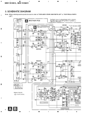
SCHEMATIC DIAGRAM A Note: When ordering service parts, be sure to refer to "EXPLODED VIEWS AND PARTS LIST" or "ELECTRICAL PARTS LIST". THRU-PUT A MOTHER PCB GM-X424 only A Lch B ISOLATOR PCB LPF / HPF R179, 180 : GM-X324 only VR153 : GM-X424 only BASS B A Rch ISOLATOR B Lch C ISOLATOR B Rch AMP UNIT Consists of MOTHER PCB ISOLATOR PCB SIGNAL ROUTE : AUDIO SIGNAL D 6 AB 1 2 DC-DC CONVERTER 3 FLAT A HPF FLAT A SWITCHING CONTROL OVER VOLTA DETECTOR S601, R641 : ES and EW models only THERMO-DETECTOR 4 1 2 3 4 GM-X424, GM-X324 3.
SCHEMATIC DIAGRAM A Note: When ordering service parts, be sure to refer to "EXPLODED VIEWS AND PARTS LIST" or "ELECTRICAL PARTS LIST". THRU-PUT A MOTHER PCB GM-X424 only A Lch B ISOLATOR PCB LPF / HPF R179, 180 : GM-X324 only VR153 : GM-X424 only BASS B A Rch ISOLATOR B Lch C ISOLATOR B Rch AMP UNIT Consists of MOTHER PCB ISOLATOR PCB SIGNAL ROUTE : AUDIO SIGNAL D 6 AB 1 2 DC-DC CONVERTER 3 FLAT A HPF FLAT A SWITCHING CONTROL OVER VOLTA DETECTOR S601, R641 : ES and EW models only THERMO-DETECTOR 4 1 2 3 4 GM-X424, GM-X324 3.
Service Manual
Page 7
5 6 7 8 GM-X424, GM-X324 A BASS BOOST 4R7/50 BUFFER AMP PRE DRIVER POWER AMP OVER CURRENT DETECTOR OVER VOLTAGE DETECTOR 4R7/50 B FLAT AMP FLAT AMP MUTE MUTE POWER CONTROL / MUTE 22/50 R VOLTAGE TETECTOR 5 6 POWER DETECTOR C OVER CURRENT PROTECTOR & OVER VOLTAGE PROTECTOR ES and EW models only GROUND WIRE BATTERY WIRE SYSTEM REMOTE CONTROL D Fig. 3 A7 7 8
5 6 7 8 GM-X424, GM-X324 A BASS BOOST 4R7/50 BUFFER AMP PRE DRIVER POWER AMP OVER CURRENT DETECTOR OVER VOLTAGE DETECTOR 4R7/50 B FLAT AMP FLAT AMP MUTE MUTE POWER CONTROL / MUTE 22/50 R VOLTAGE TETECTOR 5 6 POWER DETECTOR C OVER CURRENT PROTECTOR & OVER VOLTAGE PROTECTOR ES and EW models only GROUND WIRE BATTERY WIRE SYSTEM REMOTE CONTROL D Fig. 3 A7 7 8

Service Manual
Page 8
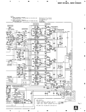
The parts mounted on this PCB 2. For further information for several destination. P.C.Board Chip Part SIDE B ADJ A MOTHER PCB A CN854 B 4 G C A CN854 B ISOLATOR PCB D 8 AB 1 2 3 4 Viewpoint of PCB diagrams include all necessary parts for Connector Capacitor SIDE A respective destinations, be sure to check with the schematic diagram. PCB CONNECTION DIAGRAM A NOTE FOR PCB DIAGRAMS 1. 1 2 3 GM-X424, GM-X324 4.
The parts mounted on this PCB 2. For further information for several destination. P.C.Board Chip Part SIDE B ADJ A MOTHER PCB A CN854 B 4 G C A CN854 B ISOLATOR PCB D 8 AB 1 2 3 4 Viewpoint of PCB diagrams include all necessary parts for Connector Capacitor SIDE A respective destinations, be sure to check with the schematic diagram. PCB CONNECTION DIAGRAM A NOTE FOR PCB DIAGRAMS 1. 1 2 3 GM-X424, GM-X324 4.
Service Manual
Page 10
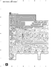
1 2 3 4 GM-X424, GM-X324 A A MOTHER PCB B C D A 10 1 2 3 4
1 2 3 4 GM-X424, GM-X324 A A MOTHER PCB B C D A 10 1 2 3 4
Service Manual
Page 12
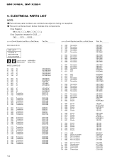
.../_S___J,RS1/__S___J Chip Capacitor (except for CQS.....) CKS....., CCS....., CSZS..... =====Circuit Symbol and No.===Part Name GM-X424/X1R/UC Part No AMP UNIT Consists of MOTHER PCB ISOLATOR PCB A B Unit Number : HWH0054 Unit Name : Amp Unit MISCELLANEOUS IC 121 IC IC 122 IC IC 123 IC IC 151 IC IC ... 1SS133 1SS133 1SS133 1SS133 1SS133 BR4361F CTH1142 CTF1007 CTF1007 CTF1007 CTF1007 HTT1035 CCX1009 CCX1013 CCX1035 12 The part numbers shown below indicate chip components. ELECTRICAL PARTS LIST NOTE: - Parts whose parts numbers are omitted are subject to being not supplied. -
.../_S___J,RS1/__S___J Chip Capacitor (except for CQS.....) CKS....., CCS....., CSZS..... =====Circuit Symbol and No.===Part Name GM-X424/X1R/UC Part No AMP UNIT Consists of MOTHER PCB ISOLATOR PCB A B Unit Number : HWH0054 Unit Name : Amp Unit MISCELLANEOUS IC 121 IC IC 122 IC IC 123 IC IC 151 IC IC ... 1SS133 1SS133 1SS133 1SS133 1SS133 BR4361F CTH1142 CTF1007 CTF1007 CTF1007 CTF1007 HTT1035 CCX1009 CCX1013 CCX1035 12 The part numbers shown below indicate chip components. ELECTRICAL PARTS LIST NOTE: - Parts whose parts numbers are omitted are subject to being not supplied. -
Service Manual
Page 13
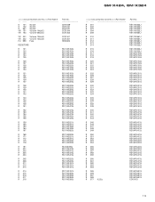
GM-X424, GM-X324 =====Circuit Symbol and No.===Part Name S 101 S 102 S 851 VR 151 VR 153 Switch Switch Switch Volume 10kΩ(C) Volume 50kΩ(C) VR 201 VR 202 FU 999 Volume 10kΩ(A) Volume 10kΩ(A) Fuse RESISTORS R 121 R 122 R 123 R 124 R 125 R 126 R 127 R 128 R 129 R 130 R 131 R 132 R 135 R 136 R 137 R... RS1/10S472J RS1/10S472J RS1/10S223J RS1/10S223J RS1/10S181J RS1/10S181J RS1/10S181J RS1/10S181J RS1/10S392J RS1/10S392J RS1/10S392J RS1/10S392J =====Circuit Symbol and No.===Part Name R 301 R 302 R 303 R 304 R 309 R 310 R 311 R 312 R 313 R 314 R 315 R 316 R 317 R...
GM-X424, GM-X324 =====Circuit Symbol and No.===Part Name S 101 S 102 S 851 VR 151 VR 153 Switch Switch Switch Volume 10kΩ(C) Volume 50kΩ(C) VR 201 VR 202 FU 999 Volume 10kΩ(A) Volume 10kΩ(A) Fuse RESISTORS R 121 R 122 R 123 R 124 R 125 R 126 R 127 R 128 R 129 R 130 R 131 R 132 R 135 R 136 R 137 R... RS1/10S472J RS1/10S472J RS1/10S223J RS1/10S223J RS1/10S181J RS1/10S181J RS1/10S181J RS1/10S181J RS1/10S392J RS1/10S392J RS1/10S392J RS1/10S392J =====Circuit Symbol and No.===Part Name R 301 R 302 R 303 R 304 R 309 R 310 R 311 R 312 R 313 R 314 R 315 R 316 R 317 R...
Service Manual
Page 15
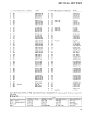
...GM-X424/X1R/UC GM-X424/X1R/ES GM-X424/X1R/EW GM-X324/X1R/UC S601 Switch Not used HSH-156 HSH-156 Not used V153 Volume 50kΩ(C) CCS1242 CCS1242 CCS1242 Not used R179, 180 Not used Not used Not used RD1/10S223J R641 Not used RD1/4PU105J RD1/4PU105J Not used 15 Amp Unit Part No. GM-X424, GM-X324 =====Circuit Symbol and No.===Part... CFTNA333J50 CFTNA333J50 CFTNA333J50 CFTNA333J50 CKSQYB102K50 CKSQYB102K50 CKSQYB102K50 CKSQYB102K50 CFTNA105J50 CFTNA103J50 CCH1183 CEAS470M16 CEAS220M50 =====Circuit Symbol and No.===Part Name C 607 C 608 C 609 C 610 C 611 C 612 3300...
...GM-X424/X1R/UC GM-X424/X1R/ES GM-X424/X1R/EW GM-X324/X1R/UC S601 Switch Not used HSH-156 HSH-156 Not used V153 Volume 50kΩ(C) CCS1242 CCS1242 CCS1242 Not used R179, 180 Not used Not used Not used RD1/10S223J R641 Not used RD1/4PU105J RD1/4PU105J Not used 15 Amp Unit Part No. GM-X424, GM-X324 =====Circuit Symbol and No.===Part... CFTNA333J50 CFTNA333J50 CFTNA333J50 CFTNA333J50 CKSQYB102K50 CKSQYB102K50 CKSQYB102K50 CKSQYB102K50 CFTNA105J50 CFTNA103J50 CCH1183 CEAS470M16 CEAS220M50 =====Circuit Symbol and No.===Part Name C 607 C 608 C 609 C 610 C 611 C 612 3300...
Service Manual
Page 16
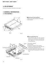
... screws A, and then remove case. 2. ADJUSTMENT There is no information to remove the Amp Unit from the Heat Sink. Remove panel. of screw B and insert them little by little until the Sub Heat Sink separates from the Heat Sink. GENERAL INFORMATION 7.1 DISASSEMBLY A - therefore, to be shown in this chapter. 7. Sub Heat Sink Heat Sink Fig. 7 Remove two screws D. 2. GM-X424, GM...
... screws A, and then remove case. 2. ADJUSTMENT There is no information to remove the Amp Unit from the Heat Sink. Remove panel. of screw B and insert them little by little until the Sub Heat Sink separates from the Heat Sink. GENERAL INFORMATION 7.1 DISASSEMBLY A - therefore, to be shown in this chapter. 7. Sub Heat Sink Heat Sink Fig. 7 Remove two screws D. 2. GM-X424, GM...
Service Manual
Page 17
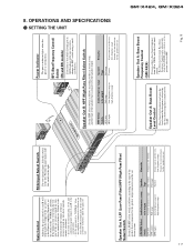
...speaker output connector and the car stereo system: LPF/HPF Select Switch LPF (left . RCA Input Select Switch For two-channel input, slide this switch to the left ) OFF (center) HPF (right) Audio frequency range to be adjusted only when the LPF/HPF select switch is set the switch to 12 dB. Power Indicator The power indicator lights when the power is too low or distorts, adjust the gain control. Fig. 8 8. For four-channel input, slide this amplifier is connected to a Pioneer car stereo with the bass boost control. • Bass Boost Level Control, Bass Boost Frequency...
...speaker output connector and the car stereo system: LPF/HPF Select Switch LPF (left . RCA Input Select Switch For two-channel input, slide this switch to the left ) OFF (center) HPF (right) Audio frequency range to be adjusted only when the LPF/HPF select switch is set the switch to 12 dB. Power Indicator The power indicator lights when the power is too low or distorts, adjust the gain control. Fig. 8 8. For four-channel input, slide this amplifier is connected to a Pioneer car stereo with the bass boost control. • Bass Boost Level Control, Bass Boost Frequency...
Service Manual
Page 18
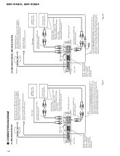
...blue wire of the car stereo (SYSTEM REMOTE CONTROL). Ground wire (black) [RD-222] (sold separately). RCA input jack A, B Connecting wires with RCA pin plugs (sold separately) Amplifier with RCA input jacks Car stereo with RCA output jacks RCA output jack Fuse (25A) External Output For details on how to connect to metal body or chassis. If only input pin plug, do not connect anything to metal body or chassis. Speaker output terminal See the "Connecting the Speakers and Input wires" section for speaker connection instructions. CONNECTION DIAGRAM (1) GM-X424/X1R/UC Grommet Fuse...
...blue wire of the car stereo (SYSTEM REMOTE CONTROL). Ground wire (black) [RD-222] (sold separately). RCA input jack A, B Connecting wires with RCA pin plugs (sold separately) Amplifier with RCA input jacks Car stereo with RCA output jacks RCA output jack Fuse (25A) External Output For details on how to connect to metal body or chassis. If only input pin plug, do not connect anything to metal body or chassis. Speaker output terminal See the "Connecting the Speakers and Input wires" section for speaker connection instructions. CONNECTION DIAGRAM (1) GM-X424/X1R/UC Grommet Fuse...
Service Manual
Page 19
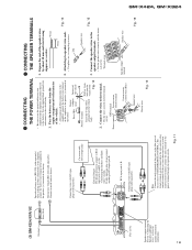
... ignition switch. If the car stereo does not have a system remote control terminal, connect the male terminal to the speaker output terminals. Connecting wires with the terminal screws. Fig. 11 Battery wire Fig. 13 Use the supplied black ground wire and connect to the terminal. • Fix the wires securely with RCA pin plugs (sold separately). - Drill an 8-mm hole into the vehicle body. Connect the wires to the vehicle body. 1. GM-X424, GM-X324 19 (3) GM-X324/X1R/UC Grommet Fuse (30 A) Fuse (25 A) Speaker output terminal...
... ignition switch. If the car stereo does not have a system remote control terminal, connect the male terminal to the speaker output terminals. Connecting wires with the terminal screws. Fig. 11 Battery wire Fig. 13 Use the supplied black ground wire and connect to the terminal. • Fix the wires securely with RCA pin plugs (sold separately). - Drill an 8-mm hole into the vehicle body. Connect the wires to the vehicle body. 1. GM-X424, GM-X324 19 (3) GM-X324/X1R/UC Grommet Fuse (30 A) Fuse (25 A) Speaker output terminal...
Service Manual
Page 20
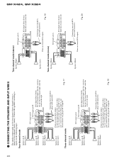
.... GM-X424, GM-X324 20 - Connecting wires with RCA plugs (sold separately) Speaker out A: Speaker (Left) From car stereo (RCA output) If only one input plug is used , such as when the car stereo has only one output (RCA output), connect the plug to RCA input A, and do not connect any plug to the left . Two-channel mode (stereo) Speaker (Right) RCA input jack A RCA Input Select Switch Slide this switch to the left . Speaker (Mono) Connecting wire with RCA plug (sold separately) From car stereo (RCA output) Fig. 20 Speaker out A: Speaker (Mono) Connecting wires with RCA plug...
.... GM-X424, GM-X324 20 - Connecting wires with RCA plugs (sold separately) Speaker out A: Speaker (Left) From car stereo (RCA output) If only one input plug is used , such as when the car stereo has only one output (RCA output), connect the plug to RCA input A, and do not connect any plug to the left . Two-channel mode (stereo) Speaker (Right) RCA input jack A RCA Input Select Switch Slide this switch to the left . Speaker (Mono) Connecting wire with RCA plug (sold separately) From car stereo (RCA output) Fig. 20 Speaker out A: Speaker (Mono) Connecting wires with RCA plug...
Service Manual
Page 21
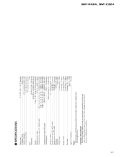
Use this value when working out total current drawn by this unit when an audio signal is nearly the maximum current drawn by multiple power amplifiers. GM-X424, GM-X324 21 SPECIFICATIONS Power source ...14.4 V DC (10.8 - 15.1 V allowable) Grounding system ...Negative type Current consumption ...18 A (at continuous power, 4 Ω) Average current drawn* ...5.5 A (4 Ω for four channels) 10 A (4 Ω for two channels) Fuse ...25 A Dimensions ...216 (W) × 52...
Use this value when working out total current drawn by this unit when an audio signal is nearly the maximum current drawn by multiple power amplifiers. GM-X424, GM-X324 21 SPECIFICATIONS Power source ...14.4 V DC (10.8 - 15.1 V allowable) Grounding system ...Negative type Current consumption ...18 A (at continuous power, 4 Ω) Average current drawn* ...5.5 A (4 Ω for four channels) 10 A (4 Ω for two channels) Fuse ...25 A Dimensions ...216 (W) × 52...


