
Service Manual
Page 1
... AND SPECIFICATIONS 16 This service manual is intended for qualified service technicians; WARNING Lead in solder used in Japan it -yourselfer. When servicing or handling circuit boards and other components which may void the warranty. PIONEER ELECTRONIC CORPORATION 4-1, Meguro 1-Chome, Meguro-ku, Tokyo 153-8654, Japan PIONEER ELECTRONICS SERVICE INC. CRT2167 BRIDGEABLE POWER AMPLIFIER GM-X422 X1R/UC, ES, EW GM-X322 X1R/UC CONTENTS 1. ELECTRICAL PARTS LIST...
... AND SPECIFICATIONS 16 This service manual is intended for qualified service technicians; WARNING Lead in solder used in Japan it -yourselfer. When servicing or handling circuit boards and other components which may void the warranty. PIONEER ELECTRONIC CORPORATION 4-1, Meguro 1-Chome, Meguro-ku, Tokyo 153-8654, Japan PIONEER ELECTRONICS SERVICE INC. CRT2167 BRIDGEABLE POWER AMPLIFIER GM-X422 X1R/UC, ES, EW GM-X322 X1R/UC CONTENTS 1. ELECTRICAL PARTS LIST...
Service Manual
Page 2
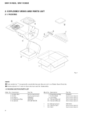
GM-X422, GM-X322 2. EXPLODED VIEWS AND PARTS LIST 2.1. Parts marked by "*"are generally unavailable because they are used for disassembly. (1) PACKING SECTION PARTS LIST Mark No. Screws adjacent to ∇ mark on the product are not in our Master Spare Parts List. - HEG0011 See Contrast table (2) See Contrast table (2) See Contrast table (2) See Contrast table (2) * 9-3 Warranty Card * 9-4 Caution Card * 9-5 Card HRY1070 See...
GM-X422, GM-X322 2. EXPLODED VIEWS AND PARTS LIST 2.1. Parts marked by "*"are generally unavailable because they are used for disassembly. (1) PACKING SECTION PARTS LIST Mark No. Screws adjacent to ∇ mark on the product are not in our Master Spare Parts List. - HEG0011 See Contrast table (2) See Contrast table (2) See Contrast table (2) See Contrast table (2) * 9-3 Warranty Card * 9-4 Caution Card * 9-5 Card HRY1070 See...

Service Manual
Page 3
... 3 Owner's Manual Model GM-X422/X1R/UC GM-X422/X1R/ES GM-X422/X1R/EW GM-X322/X1R/UC Part No. GM-X422, GM-X322 (2) CONTRAST TABLE GM-X422/X1R/UC, GM-X422/X1R/ES, GM-X422/X1R/EW and GM-X322/X1R/UC are constructed the same except for the following: Mark No. 1 2 7 8 9-1 Symbol and Description Contain Box Carton Terminal(x8) Cord Assy Owner's Manual X1R/UC HHL0134 HHG0134 HKC0001 Not used ARY1048 - GM-X422 X1R...
... 3 Owner's Manual Model GM-X422/X1R/UC GM-X422/X1R/ES GM-X422/X1R/EW GM-X322/X1R/UC Part No. GM-X422, GM-X322 (2) CONTRAST TABLE GM-X422/X1R/UC, GM-X422/X1R/ES, GM-X422/X1R/EW and GM-X322/X1R/UC are constructed the same except for the following: Mark No. 1 2 7 8 9-1 Symbol and Description Contain Box Carton Terminal(x8) Cord Assy Owner's Manual X1R/UC HHL0134 HHG0134 HKC0001 Not used ARY1048 - GM-X422 X1R...

Service Manual
Page 5
... HKE0001 Not used 31 Plate Unit HXA0166 40 System Remote Control Not used 41 Badge Unit HXA0168 43 Special Red Battery Wire Not used HXA0163 HDE0007 HXA0164 HDE4454 HXA0163 HDE0007 HXA0164 HDE4454 HXA0163 Not used HXA0164 Not used HNB0055 HNB0050 Part No. GM-X422, GM-X322 (1) EXTERIOR SECTION PARTS LIST Mark No. Description Part No. 21 Connector(CN853) HDE4418 22 Cord(CN551) HDE4610 23 Fuse(20A) HEK0020 24 Heat Sink(Sub Heat...
... HKE0001 Not used 31 Plate Unit HXA0166 40 System Remote Control Not used 41 Badge Unit HXA0168 43 Special Red Battery Wire Not used HXA0163 HDE0007 HXA0164 HDE4454 HXA0163 HDE0007 HXA0164 HDE4454 HXA0163 Not used HXA0164 Not used HNB0055 HNB0050 Part No. GM-X422, GM-X322 (1) EXTERIOR SECTION PARTS LIST Mark No. Description Part No. 21 Connector(CN853) HDE4418 22 Cord(CN551) HDE4610 23 Fuse(20A) HEK0020 24 Heat Sink(Sub Heat...

Service Manual
Page 6
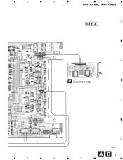
SCHEMATIC DIAGRAM Note: When ordering service parts, be sure to refer to "EXPLODED VIEWS AND PARTS LIST" or "ELECTRICAL PARTS A LIST". A MOTHER PCB SPEAKER INPUT LEVEL UC and ES models only 10/50 10/50 L C851, 852 UC, ES : 100P EW : 470P LPF / HPF R469, 470 : GM-X322 only VR452 : GM-X422 only BASS BOOST 4R7/50 MUTE B R L R R469 22k 22k R470 4R7/50 +15 REGULATOR C SWITCHING REGULATOR B ISOLATOR PCB SIGNAL ROUTE -15 REGULATOR : AUDIO SIGNAL AMP UNIT Consists of MOTHER PCB D ISOLATOR PCB 6 AB 1 2 3 THERMO-DETECTION 4 1 2 3 4 GM-X422, GM-X322 3.
SCHEMATIC DIAGRAM Note: When ordering service parts, be sure to refer to "EXPLODED VIEWS AND PARTS LIST" or "ELECTRICAL PARTS A LIST". A MOTHER PCB SPEAKER INPUT LEVEL UC and ES models only 10/50 10/50 L C851, 852 UC, ES : 100P EW : 470P LPF / HPF R469, 470 : GM-X322 only VR452 : GM-X422 only BASS BOOST 4R7/50 MUTE B R L R R469 22k 22k R470 4R7/50 +15 REGULATOR C SWITCHING REGULATOR B ISOLATOR PCB SIGNAL ROUTE -15 REGULATOR : AUDIO SIGNAL AMP UNIT Consists of MOTHER PCB D ISOLATOR PCB 6 AB 1 2 3 THERMO-DETECTION 4 1 2 3 4 GM-X422, GM-X322 3.

Service Manual
Page 7
5 6 7 8 GM-X422, GM-X322 A MUTE BUFFER AMP PRE DRIVER POWER AMP OVER CURRENT DETECTOR B 22/50 OVER CURRENT DETECTOR SWITCHING CONTROL ES and EW models only OVER VOLTAGE PROTECTOR POWER CONTROL / MUTE 5 6 C ES and EW models only HEK0015 15A GROUND WIRE BATTERY WIRE SYSTEM REMOTE CONTROL D Fig. 3 A7 7 8
5 6 7 8 GM-X422, GM-X322 A MUTE BUFFER AMP PRE DRIVER POWER AMP OVER CURRENT DETECTOR B 22/50 OVER CURRENT DETECTOR SWITCHING CONTROL ES and EW models only OVER VOLTAGE PROTECTOR POWER CONTROL / MUTE 5 6 C ES and EW models only HEK0015 15A GROUND WIRE BATTERY WIRE SYSTEM REMOTE CONTROL D Fig. 3 A7 7 8

Service Manual
Page 8
1 2 3 4 GM-X422, GM-X322 4. For further information for several destination. PCB CONNECTION DIAGRAM A NOTE FOR PCB DIAGRAMS 1. The parts mounted on this PCB include all necessary parts for respective destinations, be sure to check with the schematic diagram. 2. Viewpoint of PCB diagrams Connector Capacitor SIDE A A MOTHER PCB CORD ASSY B P.C.Board Chip Part SIDE B G G C D A 8 1 2 3 4
1 2 3 4 GM-X422, GM-X322 4. For further information for several destination. PCB CONNECTION DIAGRAM A NOTE FOR PCB DIAGRAMS 1. The parts mounted on this PCB include all necessary parts for respective destinations, be sure to check with the schematic diagram. 2. Viewpoint of PCB diagrams Connector Capacitor SIDE A A MOTHER PCB CORD ASSY B P.C.Board Chip Part SIDE B G G C D A 8 1 2 3 4
Service Manual
Page 9
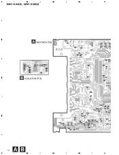
5 6 OUT IN 7 8 GM-X422, GM-X322 A SIDE A B B ISOLATOR PCB C D Fig. 4 AB 9 5 6 7 8
5 6 OUT IN 7 8 GM-X422, GM-X322 A SIDE A B B ISOLATOR PCB C D Fig. 4 AB 9 5 6 7 8
Service Manual
Page 10
1 2 3 4 GM-X422, GM-X322 A A MOTHER PCB B B ISOLATOR PCB C D A B 10 1 2 3 4
1 2 3 4 GM-X422, GM-X322 A A MOTHER PCB B B ISOLATOR PCB C D A B 10 1 2 3 4

Service Manual
Page 12
... for CQS.....) CKS....., CCS....., CSZS..... =====Circuit Symbol and No.===Part Name GM-X422/X1R/UC AMP UNIT Consists of MOTHER PCB ISOLATOR PCB A B Unit Number : HWH0059 Unit Name : Amp Unit MISCELLANEOUS IC 121 IC IC 123 IC IC...-Inductor Ferri-Inductor Choke Coil 50H Transformer Thermistor TH 902 S 101 VR 451 VR 452 VR 453 Thermistor Switch Volume 10kΩ(C) Volume 50kΩ(C) Volume 10kΩ(A) EF 902 Capacitors EF 903 Capacitors RESISTORS R 121 R 122 R 125 R 126 R 129... PARTS LIST NOTE: - GM-X422, GM-X322 5. The part numbers shown below indicate chip components.
... for CQS.....) CKS....., CCS....., CSZS..... =====Circuit Symbol and No.===Part Name GM-X422/X1R/UC AMP UNIT Consists of MOTHER PCB ISOLATOR PCB A B Unit Number : HWH0059 Unit Name : Amp Unit MISCELLANEOUS IC 121 IC IC 123 IC IC...-Inductor Ferri-Inductor Choke Coil 50H Transformer Thermistor TH 902 S 101 VR 451 VR 452 VR 453 Thermistor Switch Volume 10kΩ(C) Volume 50kΩ(C) Volume 10kΩ(A) EF 902 Capacitors EF 903 Capacitors RESISTORS R 121 R 122 R 125 R 126 R 129... PARTS LIST NOTE: - GM-X422, GM-X322 5. The part numbers shown below indicate chip components.
Service Manual
Page 14
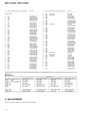
... Not used R469, 470 Not used Not used Not used RS1/10S223J R869, 872 RD1/4PU473J RD1/4PU473J Not used RD1/4PU473J R926 Not used RD1/4PU105J RD1/4PU105J Not used C851, 852 C861, 862 CCSQCH101J50 CEAS100M50 CCSQCH101J50 CEAS100M50 CKSQYB471K50 Not used CCSQCH101J50 CEAS100M50 6. ADJUSTMENT There is no information to be shown in this chapter. 14 Amp Unit Part No. GM-X422, GM-X322 =====Circuit Symbol...
... Not used R469, 470 Not used Not used Not used RS1/10S223J R869, 872 RD1/4PU473J RD1/4PU473J Not used RD1/4PU473J R926 Not used RD1/4PU105J RD1/4PU105J Not used C851, 852 C861, 862 CCSQCH101J50 CEAS100M50 CCSQCH101J50 CEAS100M50 CKSQYB471K50 Not used CCSQCH101J50 CEAS100M50 6. ADJUSTMENT There is no information to be shown in this chapter. 14 Amp Unit Part No. GM-X422, GM-X322 =====Circuit Symbol...

Service Manual
Page 15
... four screws B and Three screws C. 2. Sub Heat Sink Heat Sink Fig. 7 15 Removing the Amp Unit Some silicone glue has been applied between the Heat sink and the Sub Heat Sink. Use 2 pcs. 7. A Panel Case Fig. 6 B C Amp Unit Sub Heat Sink C B - GENERAL INFORMATION 7.1 DISASSEMBLY A GM-X422, GM-X322 - Remove six screws A, and then remove case. 2. of screw B and insert them little by little until the Sub...
... four screws B and Three screws C. 2. Sub Heat Sink Heat Sink Fig. 7 15 Removing the Amp Unit Some silicone glue has been applied between the Heat sink and the Sub Heat Sink. Use 2 pcs. 7. A Panel Case Fig. 6 B C Amp Unit Sub Heat Sink C B - GENERAL INFORMATION 7.1 DISASSEMBLY A GM-X422, GM-X322 - Remove six screws A, and then remove case. 2. of screw B and insert them little by little until the Sub...

Service Manual
Page 16
... the volume of the speaker that is too low or distorts, adjust the gain control. If the sound distorts when the volume is turned up , turn the gain control counter-clockwise. • Set the gain control to 120 Hz with RCA output jacks. GM-X422, GM-X322 8. Power Indicator The power indicator lights when the power is set to high-frequency range Speaker Type Sub-woofer Full range Tweeter Remarks Connect a sub-woofer. LPF (Low-Pass Filter)/HPF (High-Pass Filter) Select Switch Set the LPF/HPF select switch as...
... the volume of the speaker that is too low or distorts, adjust the gain control. If the sound distorts when the volume is turned up , turn the gain control counter-clockwise. • Set the gain control to 120 Hz with RCA output jacks. GM-X422, GM-X322 8. Power Indicator The power indicator lights when the power is set to high-frequency range Speaker Type Sub-woofer Full range Tweeter Remarks Connect a sub-woofer. LPF (Low-Pass Filter)/HPF (High-Pass Filter) Select Switch Set the LPF/HPF select switch as...

Service Manual
Page 17
... remote control terminal, connect the male terminal to the auto-antenna relay control terminal. Ground wire (black) [RD-222] (sold separately). External Output RCA input jack RCA input jack Fuse (20 A) Speaker output terminal See the "Connecting the Speaker wires" section for speaker connection instructions. Fig. 9 After making all other connections at the amplifier, connect the battery wire terminal of the amplifier to the auto-antenna relay control terminal. Car stereo with RCA output jacks (2) GM-X422/X1R/ES, GM-X422/X1R/EW Grommet Fuse (30 A) Special red battery wire...
... remote control terminal, connect the male terminal to the auto-antenna relay control terminal. Ground wire (black) [RD-222] (sold separately). External Output RCA input jack RCA input jack Fuse (20 A) Speaker output terminal See the "Connecting the Speaker wires" section for speaker connection instructions. Fig. 9 After making all other connections at the amplifier, connect the battery wire terminal of the amplifier to the auto-antenna relay control terminal. Car stereo with RCA output jacks (2) GM-X422/X1R/ES, GM-X422/X1R/EW Grommet Fuse (30 A) Special red battery wire...

Service Manual
Page 18
... to the power terminal through the ignition switch. Use the supplied black ground wire and connect to the terminal. • Fix the wires securely with the terminal screws. GM-X422, GM-X322 18 (3) GM-X322/X1R/UC Grommet Fuse (30 A) Fuse (20 A) Speaker terminal See the "Connecting the Speaker wires" section for speaker connection instructions. Fig. 12 2. Connect the wires to the vehicle body. 1. If the car stereo does not have a system remote control terminal, connect the male terminal to use the special red battery wire supplied with RCA output jacks External...
... to the power terminal through the ignition switch. Use the supplied black ground wire and connect to the terminal. • Fix the wires securely with the terminal screws. GM-X422, GM-X322 18 (3) GM-X322/X1R/UC Grommet Fuse (30 A) Fuse (20 A) Speaker terminal See the "Connecting the Speaker wires" section for speaker connection instructions. Fig. 12 2. Connect the wires to the vehicle body. 1. If the car stereo does not have a system remote control terminal, connect the male terminal to use the special red battery wire supplied with RCA output jacks External...
Service Manual
Page 19
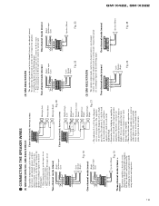
...(Right) Speaker input (Left) Three-channel mode, three-way system Fig. 20 High/mid-high C1 (Left) (Left) Speaker (Right) Fig. 18 One-channel mode (mono) (Right) Speaker input (Left) Speaker (Mono) Fig. 19 Three-channel mode (stereo + mono) The power amplifier is basically a twochannel/one -channel (mono), or threechannel (stereo + mono). CONNECTING THE SPEAKER WIRES (1) GM-X422/X1R/UC, GM-X322/X1R/UC The speaker output mode can be two-channel (stereo), one -channel bridgeable amplifier, but three channels can be achieved by combining the stereo and mono modes using inductors...
...(Right) Speaker input (Left) Three-channel mode, three-way system Fig. 20 High/mid-high C1 (Left) (Left) Speaker (Right) Fig. 18 One-channel mode (mono) (Right) Speaker input (Left) Speaker (Mono) Fig. 19 Three-channel mode (stereo + mono) The power amplifier is basically a twochannel/one -channel (mono), or threechannel (stereo + mono). CONNECTING THE SPEAKER WIRES (1) GM-X422/X1R/UC, GM-X322/X1R/UC The speaker output mode can be two-channel (stereo), one -channel bridgeable amplifier, but three channels can be achieved by combining the stereo and mono modes using inductors...

Service Manual
Page 20
... dB/oct Bass boost (GM-X422) ...Frequency: 40 - 120 Hz Gain: 0 - 12 dB Bass boost (GM-X322) ...Frequency: 60 Hz Gain: 0 - 12 dB Input level / impedance ...RCA: 0.4 - 4 V / 22 kΩ Speaker (UC and ES models): 1.6 - 10 V / 40 kΩ Note: • Specifications and the design are subject to possible modification without notice due to improvements. *Average current drawn • The average current drawn is input. Use this unit when an audio signal is...
... dB/oct Bass boost (GM-X422) ...Frequency: 40 - 120 Hz Gain: 0 - 12 dB Bass boost (GM-X322) ...Frequency: 60 Hz Gain: 0 - 12 dB Input level / impedance ...RCA: 0.4 - 4 V / 22 kΩ Speaker (UC and ES models): 1.6 - 10 V / 40 kΩ Note: • Specifications and the design are subject to possible modification without notice due to improvements. *Average current drawn • The average current drawn is input. Use this unit when an audio signal is...


