
Owners Manual
Page 2
Contents Before Using This Product 2 Composition of Manual 2 In case of trouble 2 WARNING 2 Setting the Unit 3 Gain Control 3 Power Indicator 4 BFC (Beat Frequency Control) Switch 4 LPF (Low-Pass Filter) Select Switch 4 Connecting the Unit 5 Connection Diagram 6 Connecting the Power Terminal 7 Connecting the Speaker Output Terminals ...... 7 Using the Speaker Input 8 Connecting the Speaker wires 9 Installation 10 Example of installation on the floor mat or on the chassis 10 Specifications 11 1
Contents Before Using This Product 2 Composition of Manual 2 In case of trouble 2 WARNING 2 Setting the Unit 3 Gain Control 3 Power Indicator 4 BFC (Beat Frequency Control) Switch 4 LPF (Low-Pass Filter) Select Switch 4 Connecting the Unit 5 Connection Diagram 6 Connecting the Power Terminal 7 Connecting the Speaker Output Terminals ...... 7 Using the Speaker Input 8 Connecting the Speaker wires 9 Installation 10 Example of installation on the floor mat or on the chassis 10 Specifications 11 1

Owners Manual
Page 3
... still hear normal traffic sound. • Check the connections of the power supply and speakers if the fuse of the amplifier and speakers, the protective circuit will cut the power supply to the amplifier (sound will stop) when an abnormal condition occurs. WARNING • Always use the special red battery and ground wire [RD-223], which is wet. • For traffic safety and to the car body. • Do...
... still hear normal traffic sound. • Check the connections of the power supply and speakers if the fuse of the amplifier and speakers, the protective circuit will cut the power supply to the amplifier (sound will stop) when an abnormal condition occurs. WARNING • Always use the special red battery and ground wire [RD-223], which is wet. • For traffic safety and to the car body. • Do...

Owners Manual
Page 4
Setting the Unit Gain Control If the sound level is too low, even when the volume of the car stereo used along with this power amplifier is turned up , turn gain control on the front of 4 V or more, adjust level to match the car stereo output level. • If you hear too much noise when using the speaker input terminals, turn the gain control counter-clockwise. • When using with an RCA equipped Pioneer car stereo with an RCA equipped car stereo (standard output of 500 mV), set to the...
Setting the Unit Gain Control If the sound level is too low, even when the volume of the car stereo used along with this power amplifier is turned up , turn gain control on the front of 4 V or more, adjust level to match the car stereo output level. • If you hear too much noise when using the speaker input terminals, turn the gain control counter-clockwise. • When using with an RCA equipped Pioneer car stereo with an RCA equipped car stereo (standard output of 500 mV), set to the...

Owners Manual
Page 5
... Frequency range Full range Speaker Type Subwoofer Full range Remarks Connect a subwoofer. 4 ENGLISH Power Indicator The power indicator lights when the power is connected to the speaker output connector and the car stereo system: LPF Select Switch LPF (left) OFF (right) Audio frequency range to an MW/LW broadcast with your car stereo, change the BFC switch using a small standard tip screwdriver. ESPAÑOL DEUTSCH FRANÇAIS ITALIANO NEDERLANDS LPF (Low-Pass Filter) Select Switch Set the LPF select switch...
... Frequency range Full range Speaker Type Subwoofer Full range Remarks Connect a subwoofer. 4 ENGLISH Power Indicator The power indicator lights when the power is connected to the speaker output connector and the car stereo system: LPF Select Switch LPF (left) OFF (right) Audio frequency range to an MW/LW broadcast with your car stereo, change the BFC switch using a small standard tip screwdriver. ESPAÑOL DEUTSCH FRANÇAIS ITALIANO NEDERLANDS LPF (Low-Pass Filter) Select Switch Set the LPF select switch...

Owners Manual
Page 6
... power to 8 ohms for other bridge connection. • Install and route the separately sold battery wire, ground wire, speaker wires and the amplifier as far away as possible from the wire. Before installing it may be 2 to 8 ohms for stereo connection, and 4 to other equipment by cutting the insulation of this product and those for monaural and other products may become damaged. GM-X552 Speaker Channel Two-channel One-channel GM-X352 Speaker Channel Two-channel One-channel 5 Speaker Type Subwoofer...
... power to 8 ohms for other bridge connection. • Install and route the separately sold battery wire, ground wire, speaker wires and the amplifier as far away as possible from the wire. Before installing it may be 2 to 8 ohms for stereo connection, and 4 to other equipment by cutting the insulation of this product and those for monaural and other products may become damaged. GM-X552 Speaker Channel Two-channel One-channel GM-X352 Speaker Channel Two-channel One-channel 5 Speaker Type Subwoofer...

Owners Manual
Page 7
... car stereo (SYSTEM REMOTE CONTROL). ENGLISH ESPAÑOL Connection Diagram Fuse (30 A) Grommet Fuse (30 A) Special red battery wire [RD-223] (sold separately) Connect to metal body or chassis. The female terminal can be connected to the power terminal through the ignition switch. 6 Back side System remote control wire (sold separately). Front side Connecting wires with RCA output jacks External Output DEUTSCH FRANÇAIS ITALIANO NEDERLANDS RCA input jack Speaker input terminal See the "Using the Speaker Input" section. GM-X552: Fuse (25 A) GM-X352: Fuse...
... car stereo (SYSTEM REMOTE CONTROL). ENGLISH ESPAÑOL Connection Diagram Fuse (30 A) Grommet Fuse (30 A) Special red battery wire [RD-223] (sold separately) Connect to metal body or chassis. The female terminal can be connected to the power terminal through the ignition switch. 6 Back side System remote control wire (sold separately). Front side Connecting wires with RCA output jacks External Output DEUTSCH FRANÇAIS ITALIANO NEDERLANDS RCA input jack Speaker input terminal See the "Using the Speaker Input" section. GM-X552: Fuse (25 A) GM-X352: Fuse...
Owners Manual
Page 8
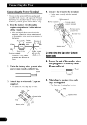
... vehicle. • After making all other connections to the amplifier, connect the battery wire terminal of the battery. Drill a 14 mm hole into the vehicle body. Expose the end of compart- Connect the wires to the positive (+) terminal of the amplifier to the terminal. • Fix the wires securely with the terminal screws. Attach lugs to speaker wire ends. Connecting the Unit Connecting the Power Terminal • Always use the special red battery and ground wire [RD-223], which...
... vehicle. • After making all other connections to the amplifier, connect the battery wire terminal of the battery. Drill a 14 mm hole into the vehicle body. Expose the end of compart- Connect the wires to the positive (+) terminal of the amplifier to the terminal. • Fix the wires securely with the terminal screws. Attach lugs to speaker wire ends. Connecting the Unit Connecting the Power Terminal • Always use the special red battery and ground wire [RD-223], which...

Owners Manual
Page 9
... terminal cover. • Fix the speaker wires securely with the terminal screws. Push on the terminal cover. ENGLISH ESPAÑOL DEUTSCH 3. Connect the speaker wires to the amplifiers using the supplied speaker input connector. • Do not connect both the RCA input and the speaker input at the same time. 7 Connections when using the speaker input Speaker output terminal Terminal cover Car Stereo Speaker wire 4. Speaker output White/black: Left ≠ White: Left + Gray/black: Right ≠ Gray: Right + Speaker input connector To speaker input terminal of this unit...
... terminal cover. • Fix the speaker wires securely with the terminal screws. Push on the terminal cover. ENGLISH ESPAÑOL DEUTSCH 3. Connect the speaker wires to the amplifiers using the supplied speaker input connector. • Do not connect both the RCA input and the speaker input at the same time. 7 Connections when using the speaker input Speaker output terminal Terminal cover Car Stereo Speaker wire 4. Speaker output White/black: Left ≠ White: Left + Gray/black: Right ≠ Gray: Right + Speaker input connector To speaker input terminal of this unit...

Owners Manual
Page 10
Two-channel mode (stereo) One-channel mode (mono) (Right) Speaker (Left) Speaker (Mono) 9 Connecting the Unit Connecting the Speaker wires The speaker output mode can be two-channel (stereo) or one-channel (mono). Connect the speaker leads to suit the mode according to the figures shown below. • Do not connect both the RCA input and the speaker input at the same time.
Two-channel mode (stereo) One-channel mode (mono) (Right) Speaker (Left) Speaker (Mono) 9 Connecting the Unit Connecting the Speaker wires The speaker output mode can be two-channel (stereo) or one-channel (mono). Connect the speaker leads to suit the mode according to the figures shown below. • Do not connect both the RCA input and the speaker input at the same time.

Owners Manual
Page 11
... such as fuel lines, brake lines and electrical wiring from damage. • Install tapping screws in such a way that the spare tire, jack and tools can be sure of the car, which can result in fire. • To prevent electric shock, do not install the amplifier in places where it is important to prevent wires from being cut by vibration of...
... such as fuel lines, brake lines and electrical wiring from damage. • Install tapping screws in such a way that the spare tire, jack and tools can be sure of the car, which can result in fire. • To prevent electric shock, do not install the amplifier in places where it is important to prevent wires from being cut by vibration of...

Owners Manual
Page 12
Use this value when working out total current drawn by this unit when an audio signal is input. Specifications GM-X552 Power source ...14.4 V DC (10.8 - 15.1 V allowable) Grounding system ...Negative type Current consumption ...13.2 A (at continuous power, 4 Ω) Average current drawn* ...4.4 A (4 Ω for two channels) 7.4 A (4 Ω for one channel) Fuse ...25 A Dimensions ...279 (W) × 58 (H) × 237 (D) mm Weight ...3.6 kg (Leads for wiring not included...
Use this value when working out total current drawn by this unit when an audio signal is input. Specifications GM-X552 Power source ...14.4 V DC (10.8 - 15.1 V allowable) Grounding system ...Negative type Current consumption ...13.2 A (at continuous power, 4 Ω) Average current drawn* ...4.4 A (4 Ω for two channels) 7.4 A (4 Ω for one channel) Fuse ...25 A Dimensions ...279 (W) × 58 (H) × 237 (D) mm Weight ...3.6 kg (Leads for wiring not included...

Owners Manual
Page 13
... power output 60 W × 2 / 150 W × 1 (DIN45324, +B=14.4 V) Load impedance ...4 Ω (2 - 8 Ω allowable) (Bridge connection: 4 - 8 Ω allowable) Frequency response ...10 - 50,000 Hz (+0 dB, -1 dB) Signal-to-noise ratio ...100 dB (IEC-A network) Distortion ...0.008 % (10 W, 1 kHz) Separation ...60 dB (1 kHz) Low pass filter ...Cut off frequency: 80 Hz Cut off slope: -12 dB/oct Maximum input level/impedance RCA: 6.5 V/22 kΩ (0.4 - 6.5 V) Speaker...
... power output 60 W × 2 / 150 W × 1 (DIN45324, +B=14.4 V) Load impedance ...4 Ω (2 - 8 Ω allowable) (Bridge connection: 4 - 8 Ω allowable) Frequency response ...10 - 50,000 Hz (+0 dB, -1 dB) Signal-to-noise ratio ...100 dB (IEC-A network) Distortion ...0.008 % (10 W, 1 kHz) Separation ...60 dB (1 kHz) Low pass filter ...Cut off frequency: 80 Hz Cut off slope: -12 dB/oct Maximum input level/impedance RCA: 6.5 V/22 kΩ (0.4 - 6.5 V) Speaker...

Owners Manual
Page 76
... CANADA, INC. 300 Allstate Parkway, Markham, Ontario L3R OP2, Canada TEL: (905) 479-4411 PIONEER ELECTRONICS DE MEXICO, S.A. Del Valle Mexico, D.F. All rights reserved. Printed in U.S.A. TEL: (800) 421-1404 PIONEER EUROPE NV Haven 1087, Keetberglaan 1, B-9120 Melsele, Belgium TEL: (0) 3/570.05.11 PIONEER ELECTRONICS AUSTRALIA PTY. P.O. Piso Desp. 302 Col. Copyright © 2000...
... CANADA, INC. 300 Allstate Parkway, Markham, Ontario L3R OP2, Canada TEL: (905) 479-4411 PIONEER ELECTRONICS DE MEXICO, S.A. Del Valle Mexico, D.F. All rights reserved. Printed in U.S.A. TEL: (800) 421-1404 PIONEER EUROPE NV Haven 1087, Keetberglaan 1, B-9120 Melsele, Belgium TEL: (0) 3/570.05.11 PIONEER ELECTRONICS AUSTRALIA PTY. P.O. Piso Desp. 302 Col. Copyright © 2000...


