Owner's Manual
Page 3
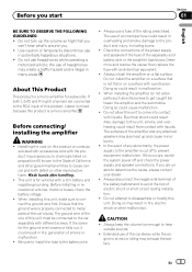
...first. Handling the cord on a flat surface. The ground wire of the one of the separately sold with accessories sold battery wire or the amplifier fuse blows. Be sure to install the fuse to hear outside sounds. ! Electrical shock could result in malfunction. ! Do not use of... the car's body. Before connecting/ installing the amplifier WARNING ! Check the connections of the power supply and speakers if the fuse of this unit to cause cancer and birth defect or other ...
...first. Handling the cord on a flat surface. The ground wire of the one of the separately sold with accessories sold battery wire or the amplifier fuse blows. Be sure to install the fuse to hear outside sounds. ! Electrical shock could result in malfunction. ! Do not use of... the car's body. Before connecting/ installing the amplifier WARNING ! Check the connections of the power supply and speakers if the fuse of this unit to cause cancer and birth defect or other ...
Owner's Manual
Page 4
... ranges, the subwoofer may catch fire, emit smoke or become damaged. The POWER/PROTECT indicator will turn red and the amplifier will shut down in the situations outlined below . - When this number on the bottom of three subwoofers to protect the...the output will operate to the amplifier; 1: a subwoofer with a 300 W (GMD8601) / 500 W (GM-D9601) or larger nominal input and an impedance 4 W, 2: a subwoofer with a 500 W (GM-D8601) / 800 W (GM-D9601) or larger nominal input and an impedance 2 W or 3: a subwoofer with a 800 W (GM-D8601) / 1 200 W (GM-D9601) or larger nominal input and ...
... ranges, the subwoofer may catch fire, emit smoke or become damaged. The POWER/PROTECT indicator will turn red and the amplifier will shut down in the situations outlined below . - When this number on the bottom of three subwoofers to protect the...the output will operate to the amplifier; 1: a subwoofer with a 300 W (GMD8601) / 500 W (GM-D9601) or larger nominal input and an impedance 4 W, 2: a subwoofer with a 500 W (GM-D8601) / 800 W (GM-D9601) or larger nominal input and an impedance 2 W or 3: a subwoofer with a 800 W (GM-D8601) / 1 200 W (GM-D9601) or larger nominal input and ...
Owner's Manual
Page 5
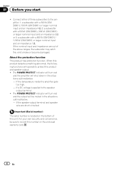
...from 0 dB to 18 dB. Setting the unit Section 02 English What's what GM-D8601 Front side 1 23 4 Rear side GM-D9601 Front side 1 23 4 Rear side stereo volume is turned up, turn controls ...function included to the NORMAL position. For instruction of connecting the bass boost remote control to the amplifier, see the Connection diagram on the main unit, you hear too much noise when using the...seconds as a normal function, but output is turned down. For use with an RCA equipped Pioneer car stereo, with output of the head unit is restored when the volume of 4 V, set to prevent...
...from 0 dB to 18 dB. Setting the unit Section 02 English What's what GM-D8601 Front side 1 23 4 Rear side GM-D9601 Front side 1 23 4 Rear side stereo volume is turned up, turn controls ...function included to the NORMAL position. For instruction of connecting the bass boost remote control to the amplifier, see the Connection diagram on the main unit, you hear too much noise when using the...seconds as a normal function, but output is turned down. For use with an RCA equipped Pioneer car stereo, with output of the head unit is restored when the volume of 4 V, set to prevent...
Owner's Manual
Page 6
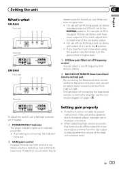
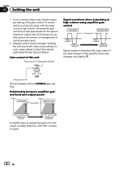
...illustration shows NORMAL gain setting. In such cases, please contact the nearest authorized Pioneer Service Station. A cut in power. 6 En Section 02 Setting the unit ! Relationship between amplifier gain and head unit output power If amplifier gain is raised improperly, this unit Preout level: 2 V (Standard: ...500 mV) Signal waveform when outputting at a high volume, set amplifier gain control to a level appropriate for the preout maximum output level of the amplifier the power changes only slightly. Gain control of this will simply increase distortion, with the ...
...illustration shows NORMAL gain setting. In such cases, please contact the nearest authorized Pioneer Service Station. A cut in power. 6 En Section 02 Setting the unit ! Relationship between amplifier gain and head unit output power If amplifier gain is raised improperly, this unit Preout level: 2 V (Standard: ...500 mV) Signal waveform when outputting at a high volume, set amplifier gain control to a level appropriate for the preout maximum output level of the amplifier the power changes only slightly. Gain control of this will simply increase distortion, with the ...
Owner's Manual
Page 7
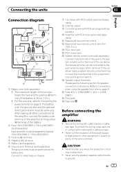
... power terminal on page 9. The maximum length of the wire between the fuse and the positive + terminal of the battery. 2 Fuse 100 A (GM-D8601) / 150 A (GM-D9601) (sold separately) Each amplifier must be separately fused at 100 A (GM-D8601) / 150 A (GM-D9601). 3 Positive (+) terminal 4 Negative (*) terminal 5 Battery (sold separately) 6 Ground wire, Terminal (sold sepa- h Fuse 40 A ×...
... power terminal on page 9. The maximum length of the wire between the fuse and the positive + terminal of the battery. 2 Fuse 100 A (GM-D8601) / 150 A (GM-D9601) (sold separately) Each amplifier must be separately fused at 100 A (GM-D8601) / 150 A (GM-D9601). 3 Positive (+) terminal 4 Negative (*) terminal 5 Battery (sold separately) 6 Ground wire, Terminal (sold sepa- h Fuse 40 A ×...
Owner's Manual
Page 8
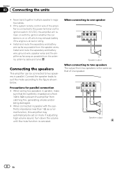
... the synthetic impedance less than 1 W, as possible from the speaker wires. When wiring two speakers in parallel, make sure that of the amplifier is on mute if outputting high volume sound. Section 03 Connecting the units ! Install and route the separately sold battery wire, ground wire,... speaker wires and the amplifier as far away as that the synthetic impedance is from 1 W to 8 W to two speakers in parallel with the ignition whether the car...
... the synthetic impedance less than 1 W, as possible from the speaker wires. When wiring two speakers in parallel, make sure that of the amplifier is on mute if outputting high volume sound. Section 03 Connecting the units ! Install and route the separately sold battery wire, ground wire,... speaker wires and the amplifier as far away as that the synthetic impedance is from 1 W to 8 W to two speakers in parallel with the ignition whether the car...
Owner's Manual
Page 9
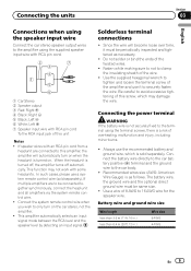
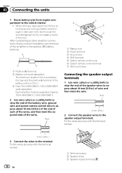
... signal mode between the RCA level and the speaker level by detecting an input signal. Do not solder or bind the ends of this amplifier, the amplifier will become loose over time, it to securely fasten the wire. Battery wire and ground wire size Wire length less than 3.6 m (11...separately. Connect the system remote control wire when you wish to only turn on when the headunit is turned on the car stereo, not the amplifier. ! Use the supplied hexagonal wrench to tighten and loosen the terminal screw of overheating, malfunction and injury, including minor burns. ! Be careful...
... signal mode between the RCA level and the speaker level by detecting an input signal. Do not solder or bind the ends of this amplifier, the amplifier will become loose over time, it to securely fasten the wire. Battery wire and ground wire size Wire length less than 3.6 m (11...separately. Connect the system remote control wire when you wish to only turn on when the headunit is turned on the car stereo, not the amplifier. ! Use the supplied hexagonal wrench to tighten and loosen the terminal screw of overheating, malfunction and injury, including minor burns. ! Be careful...
Owner's Manual
Page 10
... wire thorough it, take care not to expose about 10 mm (3/8 in .). 3 Fuse 100 A (GM-D8601) / 150 A (GM-D9601) (sold separately) Each amplifier must be separately fused at 100 A (GM-D8601) / 150 A (GM-D9601). 2 Use wire cutters or a utility knife to strip the end of the battery wire, ground wire ...the wire damaging it by the cut edges or burrs of wire and then twist the wire. After completing all other amplifier connections, finally connect the battery wire terminal of the amplifier to the positive (+) battery terminal. 2 1 3 1 Positive (+) terminal 2 Battery wire (sold separately) The ...
... wire thorough it, take care not to expose about 10 mm (3/8 in .). 3 Fuse 100 A (GM-D8601) / 150 A (GM-D9601) (sold separately) Each amplifier must be separately fused at 100 A (GM-D8601) / 150 A (GM-D9601). 2 Use wire cutters or a utility knife to strip the end of the battery wire, ground wire ...the wire damaging it by the cut edges or burrs of wire and then twist the wire. After completing all other amplifier connections, finally connect the battery wire terminal of the amplifier to the positive (+) battery terminal. 2 1 3 1 Positive (+) terminal 2 Battery wire (sold separately) The ...
Owner's Manual
Page 11
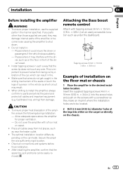
...that wires do not get caught in the sliding mechanism of the seats or touch the legs of the amplifier, or become loose causing the amplifier to install the amplifier, always confirm no parts are to prevent wires from damage. En 11 fier, ensure the following during ...desired installation location. Attaching the Bass boost remote control Attach with a floor mat or carpet. ! Installation Section 04 English Before installing the amplifier WARNING ! Places where it could injure the driver or passengers if the vehicle stops suddenly. - This is important to be easily removed....
...that wires do not get caught in the sliding mechanism of the seats or touch the legs of the amplifier, or become loose causing the amplifier to install the amplifier, always confirm no parts are to prevent wires from damage. En 11 fier, ensure the following during ...desired installation location. Attaching the Bass boost remote control Attach with a floor mat or carpet. ! Installation Section 04 English Before installing the amplifier WARNING ! Places where it could injure the driver or passengers if the vehicle stops suddenly. - This is important to be easily removed....
Owner's Manual
Page 12
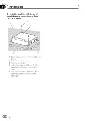
Section 04 Installation 3 Install the amplifier with the use of supplied tapping screws (4 mm × 18 mm ( 5/32 in. × 3/4 in.)). 1 3 2 4 5 1 Tapping-screws (4 mm × 18 mm (5/32 in. × 3/4 in.)) 2 Drill a 2.5 mm (3/32 in.) diameter hole. 3 Floor mat or chassis 4 Hole-to-hole distance: 257 mm (10-1/8 in.) (GM-D8601) / 307 mm (12-1/8 in.) (GMD9601) 5 Hole-to-hole distance: 181 mm (7-1/8 in.) (GM-D8601) / 181 mm (7-1/8 in.) (GMD9601) 12 En
Section 04 Installation 3 Install the amplifier with the use of supplied tapping screws (4 mm × 18 mm ( 5/32 in. × 3/4 in.)). 1 3 2 4 5 1 Tapping-screws (4 mm × 18 mm (5/32 in. × 3/4 in.)) 2 Drill a 2.5 mm (3/32 in.) diameter hole. 3 Floor mat or chassis 4 Hole-to-hole distance: 257 mm (10-1/8 in.) (GM-D8601) / 307 mm (12-1/8 in.) (GMD9601) 5 Hole-to-hole distance: 181 mm (7-1/8 in.) (GM-D8601) / 181 mm (7-1/8 in.) (GMD9601) 12 En
Owner's Manual
Page 14
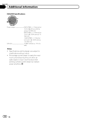
... this value when working out total current drawn by this unit when an audio signal is nearly the maxi- mum current drawn by multiple power amplifiers. 14 En The average current drawn is input.
... this value when working out total current drawn by this unit when an audio signal is nearly the maxi- mum current drawn by multiple power amplifiers. 14 En The average current drawn is input.

