Owner's Manual
Page 2
Contents Before you start Information to User 3 After-sales service for Pioneer products 3 Visit our website 3 Before connecting/installing the amplifier 4 Setting the Unit What's what 5 Setting gain properly 5 Connecting the units Connection diagram 7 Before...bridged mode 8 About suitable specification of speaker 8 Connecting the speakers 8 Connections when using the RCA input jack 10 Connections when using the speaker input wire 10 Connecting the power terminal 11 Connecting the speaker output terminals 12 Installation Before installing the amplifier 13 Example of installation on the floor mat...
Contents Before you start Information to User 3 After-sales service for Pioneer products 3 Visit our website 3 Before connecting/installing the amplifier 4 Setting the Unit What's what 5 Setting gain properly 5 Connecting the units Connection diagram 7 Before...bridged mode 8 About suitable specification of speaker 8 Connecting the speakers 8 Connections when using the RCA input jack 10 Connections when using the speaker input wire 10 Connecting the power terminal 11 Connecting the speaker output terminals 12 Installation Before installing the amplifier 13 Example of installation on the floor mat...
Owner's Manual
Page 4
... result in malfunction. ! Do not install the amplifier on a surface that the ground wire is located on a flat surface. Electrical shock could cause malfunction. ! sociated with accessories sold battery wire or the amplifier fuse blows. Disconnect the negative terminal of any attached speakers may exhaust...of the battery before installation. This unit is cut off to prevent equipment malfunction. Extended use of a special red battery and ground wire RD-223, available separately, is not flat or on this number on the enclosed warranty card. 4 En Section 01 Before you ...
... result in malfunction. ! Do not install the amplifier on a surface that the ground wire is located on a flat surface. Electrical shock could cause malfunction. ! sociated with accessories sold battery wire or the amplifier fuse blows. Disconnect the negative terminal of any attached speakers may exhaust...of the battery before installation. This unit is cut off to prevent equipment malfunction. Extended use of a special red battery and ground wire RD-223, available separately, is not flat or on this number on the enclosed warranty card. 4 En Section 01 Before you ...
Owner's Manual
Page 7
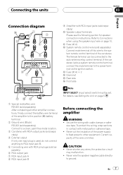
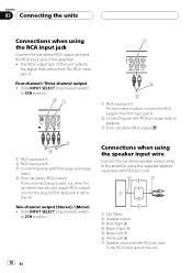
...pin plugs (sold separately) 6 RCA output jack 7 RCA input jack A 8 RCA input jack B Before connecting the amplifier WARNING ! Never wire the speaker negative cable directly- Current capacity of the car stereo. If the car stereo lacks a system remote control terminal, connect the male ...215; 2 e Grommet f Rear side g Front side Note INPUT SELECT (input select) switch must be connected to RCA input jack B. 5 Connecting wire with RCA input jacks (sold separately) After completing all other equipment. Never cut the insulation of the power supply to feed power to other amplifier...
...pin plugs (sold separately) 6 RCA output jack 7 RCA input jack A 8 RCA input jack B Before connecting the amplifier WARNING ! Never wire the speaker negative cable directly- Current capacity of the car stereo. If the car stereo lacks a system remote control terminal, connect the male ...215; 2 e Grommet f Rear side g Front side Note INPUT SELECT (input select) switch must be connected to RCA input jack B. 5 Connecting wire with RCA input jacks (sold separately) After completing all other equipment. Never cut the insulation of the power supply to feed power to other amplifier...
Owner's Manual
Page 8
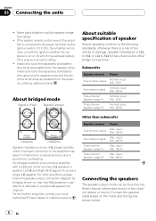
...the mode and the figures shown below. 8 En Improper connection to burns from overheating. For any further enquiries, contact your local authorized Pioneer dealer or customer service. For other bridge connections. input: Min. 150 W Three-channel Speaker output B Max. Section 03 Connecting ...the units ! Install and route the separately sold battery wire as far as possible from the speaker wires. Install and route the separately sold battery wire, ground wire, speaker wires and the amplifier as far away as possible from the antenna, antenna cable and...
...the mode and the figures shown below. 8 En Improper connection to burns from overheating. For any further enquiries, contact your local authorized Pioneer dealer or customer service. For other bridge connections. input: Min. 150 W Three-channel Speaker output B Max. Section 03 Connecting ...the units ! Install and route the separately sold battery wire as far as possible from the speaker wires. Install and route the separately sold battery wire, ground wire, speaker wires and the amplifier as far away as possible from the antenna, antenna cable and...
Owner's Manual
Page 10
... 2 Speaker output 3 Red: Right + 4 Black: Right * 5 Black: Left * 6 White: Left + 7 Speaker input wire with RCA plugs (sold separately) 3 From car stereo (RCA output) 1 RCA input jack A 2 RCA input jack B 3 Connecting wires with RCA pin cord To the RCA input jack of this unit outputs the signal that comes... amplifier. ! rately) 4 From car stereo (RCA output) If only one output (RCA output), connect the plug to the RCA input jack A. 2 Connecting wire with RCA pin plugs (sold sepa- when the car stereo has only one input plug is used, e.g. Two-channel output (Stereo) / (Mono) ! Slide...
... 2 Speaker output 3 Red: Right + 4 Black: Right * 5 Black: Left * 6 White: Left + 7 Speaker input wire with RCA plugs (sold separately) 3 From car stereo (RCA output) 1 RCA input jack A 2 RCA input jack B 3 Connecting wires with RCA pin cord To the RCA input jack of this unit outputs the signal that comes... amplifier. ! rately) 4 From car stereo (RCA output) If only one output (RCA output), connect the plug to the RCA input jack A. 2 Connecting wire with RCA pin plugs (sold sepa- when the car stereo has only one input plug is used, e.g. Two-channel output (Stereo) / (Mono) ! Slide...
Owner's Manual
Page 11
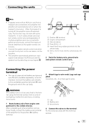
... to the vehicle interior. In such cases, please use of the amplifier to the positive (+) battery terminal. 1 Lug 2 Battery wire 3 Ground wire 4 Connect the wires to this amplifier, the amplifier will automatically turn on when the headunit is a risk of overheating, malfunction and injury, including minor burns...body. 6 Drill a 14 mm hole into the vehicle body (1/2 in.) . 2 Twist the battery wire, ground wire and system remote control wire. Lugs not supplied. WARNING If the battery wire is not securely fixed to the terminal using the terminal screws, there is turned on the car stereo, ...
... to the vehicle interior. In such cases, please use of the amplifier to the positive (+) battery terminal. 1 Lug 2 Battery wire 3 Ground wire 4 Connect the wires to this amplifier, the amplifier will automatically turn on when the headunit is a risk of overheating, malfunction and injury, including minor burns...body. 6 Drill a 14 mm hole into the vehicle body (1/2 in.) . 2 Twist the battery wire, ground wire and system remote control wire. Lugs not supplied. WARNING If the battery wire is not securely fixed to the terminal using the terminal screws, there is turned on the car stereo, ...
Owner's Manual
Page 12
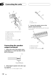
...a cutter by about 10 mm (3/8 in.) and twist. Lugs not supplied. Fix the speaker wires securely with the terminal screws. Twist 1 Terminal screws 2 Speaker wires 3 Speaker output terminals 2 Attach lugs to the speaker output terminals. Section 03 Connecting the units... 1 System remote control terminal 2 GND terminal 3 Power terminal 4 Terminal screws 5 Battery wire 6 Ground wire 7 System remote control wire 1 Lug 2 Speaker wire 3 Connect the speaker wires to speaker wire ...
...a cutter by about 10 mm (3/8 in.) and twist. Lugs not supplied. Fix the speaker wires securely with the terminal screws. Twist 1 Terminal screws 2 Speaker wires 3 Speaker output terminals 2 Attach lugs to the speaker output terminals. Section 03 Connecting the units... 1 System remote control terminal 2 GND terminal 3 Power terminal 4 Terminal screws 5 Battery wire 6 Ground wire 7 System remote control wire 1 Lug 2 Speaker wire 3 Connect the speaker wires to speaker wire ...
Owner's Manual
Page 13
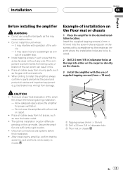
... push on the car model. CAUTION ! Check all cables away from damage. After installing the amplifier, confirm that the screw tip does not touch any wire. To ensure proper heat dissipation of a sudden stop. ! it may cause injury to be easily removed. 1 Tapping-screws (4 mm × 18 mm) ...tire, jack and tools can result in .) diameter holes at a sufficiently rigid location. ! The optimal installation location differs de- fuel/brake lines, wiring) from moving parts, such as a result of the ampli- Do not cover the amplifier with a floor mat or carpet. ! fier, ensure the...
... push on the car model. CAUTION ! Check all cables away from damage. After installing the amplifier, confirm that the screw tip does not touch any wire. To ensure proper heat dissipation of a sudden stop. ! it may cause injury to be easily removed. 1 Tapping-screws (4 mm × 18 mm) ...tire, jack and tools can result in .) diameter holes at a sufficiently rigid location. ! The optimal installation location differs de- fuel/brake lines, wiring) from moving parts, such as a result of the ampli- Do not cover the amplifier with a floor mat or carpet. ! fier, ensure the...
Owner's Manual
Page 14
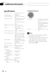
... channels) 10.7 A (2 W for four channels) Fuse 40 A × 1 Dimensions (W × H × D) ... 245 × 56 × 200 mm (9-5/8 × 2-1/4 × 7-7/8 in.) Weight 2.2 kg (4.9 lbs) (Leads for wiring not included) Maximum power output ....... 150 W × 4 (4 W) / 400 W × 2 (4 W) Continuous power output ... 75 W × 4 (at 14.4 V, 4 W, 20 Hz to 20 kHz, ≦ 1% THD) 200 W ×...
... channels) 10.7 A (2 W for four channels) Fuse 40 A × 1 Dimensions (W × H × D) ... 245 × 56 × 200 mm (9-5/8 × 2-1/4 × 7-7/8 in.) Weight 2.2 kg (4.9 lbs) (Leads for wiring not included) Maximum power output ....... 150 W × 4 (4 W) / 400 W × 2 (4 W) Continuous power output ... 75 W × 4 (at 14.4 V, 4 W, 20 Hz to 20 kHz, ≦ 1% THD) 200 W ×...


