Owner's Manual
Page 3
... supply and speakers if the fuse of an improper fuse could result from contact with liquids. CAUTION ! sociated with accessories sold battery wire or the amplifier fuse blows. Extended use headphones while operating a motorized vehicle; Before you to the product and injury, including burns.... in recreational vehicles, trucks or buses, check the battery voltage. ! Also, damage to this unit must be connected to the battery wire. ! If this unit. Always disconnect the negative * terminal of the battery beforehand to metal parts of headphones may exhaust the battery....
... supply and speakers if the fuse of an improper fuse could result from contact with liquids. CAUTION ! sociated with accessories sold battery wire or the amplifier fuse blows. Extended use headphones while operating a motorized vehicle; Before you to the product and injury, including burns.... in recreational vehicles, trucks or buses, check the battery voltage. ! Also, damage to this unit must be connected to the battery wire. ! If this unit. Always disconnect the negative * terminal of the battery beforehand to metal parts of headphones may exhaust the battery....
Owner's Manual
Page 4
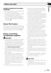
... of the above ranges, the subwoofer may catch fire, emit smoke or become damaged. If the speaker output terminal and speaker wire are out of three subwoofers to record this unit. Section 01 Before you start ! About the protection function This product has... 1: a subwoofer with a 300 W (GMD8601) / 500 W (GM-D9601) or larger nominal input and an impedance 4 W, 2: a subwoofer with a 500 W (GM-D8601) / 800 W (GM-D9601) or larger nominal input and an impedance 2 W or 3: a subwoofer with a 800 W (GM-D8601) / 1 200 W (GM-D9601) or larger nominal input and an impedance 1 W. If the temperature...
... of the above ranges, the subwoofer may catch fire, emit smoke or become damaged. If the speaker output terminal and speaker wire are out of three subwoofers to record this unit. Section 01 Before you start ! About the protection function This product has... 1: a subwoofer with a 300 W (GMD8601) / 500 W (GM-D9601) or larger nominal input and an impedance 4 W, 2: a subwoofer with a 500 W (GM-D8601) / 800 W (GM-D9601) or larger nominal input and an impedance 2 W or 3: a subwoofer with a 800 W (GM-D8601) / 1 200 W (GM-D9601) or larger nominal input and an impedance 1 W. If the temperature...
Owner's Manual
Page 7
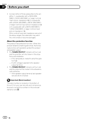
...to the positive + terminal of the battery. 2 Fuse 100 A (GM-D8601) / 150 A (GM-D9601) (sold separately) Each amplifier must be same size. Current capacity of the wire is 30 cm (12 in.). ! For the wire size, refer to Connecting the power terminal on page 9. parately) ...se- g Speaker output terminals Please see the following section for speaker connection instructions. En 7 Never wire the speaker negative cable directly- Connect to the auto-antenna relay control terminal. h Fuse 40 A × 2 (GM-D8601) / 40 A × 3 (GMD9601) i Front side j Rear side Before connecting the ...
...to the positive + terminal of the battery. 2 Fuse 100 A (GM-D8601) / 150 A (GM-D9601) (sold separately) Each amplifier must be same size. Current capacity of the wire is 30 cm (12 in.). ! For the wire size, refer to Connecting the power terminal on page 9. parately) ...se- g Speaker output terminals Please see the following section for speaker connection instructions. En 7 Never wire the speaker negative cable directly- Connect to the auto-antenna relay control terminal. h Fuse 40 A × 2 (GM-D8601) / 40 A × 3 (GMD9601) i Front side j Rear side Before connecting the ...
Owner's Manual
Page 8
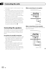
...is on or off, which may automatically be set on mute if outputting high volume sound. Install and route the separately sold battery wire, ground wire, speaker wires and the amplifier as far away as that the synthetic impedance is at rest or idling. ! Connecting the speakers This amplifier can... be connected to two speakers in parallel with the ignition whether the car stereo is canceled. Install and route the separately sold battery wire as far as possible from the antenna, antenna cable and tuner. When connected in parallel. When connecting to one speaker Speaker output ...
...is on or off, which may automatically be set on mute if outputting high volume sound. Install and route the separately sold battery wire, ground wire, speaker wires and the amplifier as far away as that the synthetic impedance is at rest or idling. ! Connecting the speakers This amplifier can... be connected to two speakers in parallel with the ignition whether the car stereo is canceled. Install and route the separately sold battery wire as far as possible from the antenna, antenna cable and tuner. When connected in parallel. When connecting to one speaker Speaker output ...
Owner's Manual
Page 9
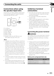
...time, it to avoid excessive tightening of the wire. ! Solderless terminal connections ! Battery wire and ground wire size Wire length less than 3.6 m (11 ft. 10 in.) less than 6.4 m (20 ft. 12 in.) Wire size 6 AWG 4 AWG En 9 Since the wire will automatically turn on . Be careful to... is sold separately). Connecting the power terminal WARNING If the battery wire is turned on the car stereo, not the amplifier. ! The battery wire, the ground wire and the optional direct ground wire must be connected together synchronously, connect the head unit and all ...
...time, it to avoid excessive tightening of the wire. ! Solderless terminal connections ! Battery wire and ground wire size Wire length less than 3.6 m (11 ft. 10 in.) less than 6.4 m (20 ft. 12 in.) Wire size 6 AWG 4 AWG En 9 Since the wire will automatically turn on . Be careful to... is sold separately). Connecting the power terminal WARNING If the battery wire is turned on the car stereo, not the amplifier. ! The battery wire, the ground wire and the optional direct ground wire must be connected together synchronously, connect the head unit and all ...
Owner's Manual
Page 10
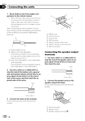
... expose about 10 mm (3/8 in .). 3 Fuse 100 A (GM-D8601) / 150 A (GM-D9601) (sold separately) Each amplifier must be separately fused at 100 A (GM-D8601) / 150 A (GM-D9601). 2 Use wire cutters or a utility knife to strip the end of the battery wire, ground wire and system remote control wire to the terminal. Fix the wires securely with the terminal screws. 1 3 2 1 Terminal screws...
... expose about 10 mm (3/8 in .). 3 Fuse 100 A (GM-D8601) / 150 A (GM-D9601) (sold separately) Each amplifier must be separately fused at 100 A (GM-D8601) / 150 A (GM-D9601). 2 Use wire cutters or a utility knife to strip the end of the battery wire, ground wire and system remote control wire to the terminal. Fix the wires securely with the terminal screws. 1 3 2 1 Terminal screws...
Owner's Manual
Page 11
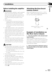
...Tapping screws (3 mm × 10 mm (1/8 in. × 3/8 in the vehicle as near the heater outlet. ! En 11 If any wire. The optimal installation location differs de- Check all cables away from hot places, such as short-circuit may interfere with a screwdriver so they may...Places where it could injure the driver or passengers if the vehicle stops suddenly. - ver, such as under the dashboard. Make sure that wires do not get caught in the desired installation location. CAUTION ! Place all connections and systems before final installation. ! Allow adequate space above ...
...Tapping screws (3 mm × 10 mm (1/8 in. × 3/8 in the vehicle as near the heater outlet. ! En 11 If any wire. The optimal installation location differs de- Check all cables away from hot places, such as short-circuit may interfere with a screwdriver so they may...Places where it could injure the driver or passengers if the vehicle stops suddenly. - ver, such as under the dashboard. Make sure that wires do not get caught in the desired installation location. CAUTION ! Place all connections and systems before final installation. ! Allow adequate space above ...
Owner's Manual
Page 13
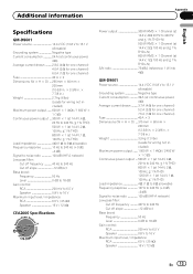
Additional information Appendix English Specifications GM-D8601 Power source 14.4 V DC (10.8 V to 15.1 V allowable) Grounding system Negative type Current consumption 24 A (at continuous power, 4 W) Average current drawn ......... 2.9 A (4 W ...Fuse 40 A × 3 Dimensions (W × H × D) ... 315 mm × 60 mm × 200 mm (12-3/8 in. × 2-3/8 in. × 7-7/8 in.) Weight 3.3 kg (7.3 lbs) (Leads for wiring not included) Maximum power output ....... 1 000 W × 1 (4 W) / 2 400 W × 1 (1 W) Continuous power output ... 500 W × 1 (at 14.4 V, 4 W, 20 Hz to 240 Hz, &#...
Additional information Appendix English Specifications GM-D8601 Power source 14.4 V DC (10.8 V to 15.1 V allowable) Grounding system Negative type Current consumption 24 A (at continuous power, 4 W) Average current drawn ......... 2.9 A (4 W ...Fuse 40 A × 3 Dimensions (W × H × D) ... 315 mm × 60 mm × 200 mm (12-3/8 in. × 2-3/8 in. × 7-7/8 in.) Weight 3.3 kg (7.3 lbs) (Leads for wiring not included) Maximum power output ....... 1 000 W × 1 (4 W) / 2 400 W × 1 (1 W) Continuous power output ... 500 W × 1 (at 14.4 V, 4 W, 20 Hz to 240 Hz, &#...


