Owner's Manual
Page 3
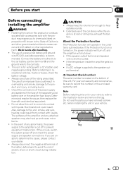
... governmental entities to cause cancer and birth defect or other reproductive harm. Electrical shock could result from contact with accessories sold battery wire or the amplifier fuse blows. If this unit to come into contact with and identical equivalent. ! Always keep the volume low...! Before installing in overheating and smoke, damage to the product and injury, including burns. ! Extended use of a special red battery and ground wire RD-223, available separately, is turned on the bottom of the separately sold with a 12 V battery and negative grounding. If a DC voltage ...
... governmental entities to cause cancer and birth defect or other reproductive harm. Electrical shock could result from contact with accessories sold battery wire or the amplifier fuse blows. If this unit to come into contact with and identical equivalent. ! Always keep the volume low...! Before installing in overheating and smoke, damage to the product and injury, including burns. ! Extended use of a special red battery and ground wire RD-223, available separately, is turned on the bottom of the separately sold with a 12 V battery and negative grounding. If a DC voltage ...
Owner's Manual
Page 6
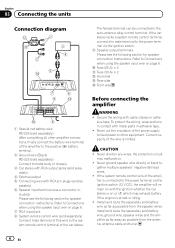
...sold separately) Connect male terminal of the car stereo. Before connecting the amplifier WARNING ! Install and route the separately sold battery wire, ground wire, speaker wires and the amplifier as far away as possible from the antenna, antenna cable and tuner. 6 En If the car stereo lacks ...insulation of the power supply to feed power to other amplifier connections, finally connect the battery wire terminal of the wire is connected to the system remote control terminal of this wire to the power terminal via the ignition switch. 9 Speaker output terminals Please see the ...
...sold separately) Connect male terminal of the car stereo. Before connecting the amplifier WARNING ! Install and route the separately sold battery wire, ground wire, speaker wires and the amplifier as far away as possible from the antenna, antenna cable and tuner. 6 En If the car stereo lacks ...insulation of the power supply to feed power to other amplifier connections, finally connect the battery wire terminal of the wire is connected to the system remote control terminal of this wire to the power terminal via the ignition switch. 9 Speaker output terminals Please see the ...
Owner's Manual
Page 7
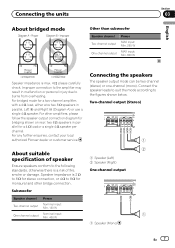
... Speaker impedance is 2 W to 8 W for stereo connection, or 4 W to 8 W for a two-channel amplifier, with a 4 W load, either wire two 8 W speakers in malfunction or personal injury due to burns from overheating. Connect the speaker leads to suit the mode according to the figures shown...7 For other bridge connection. About suitable specification of fire, smoke or damage. For any further enquiries, contact your local authorized Pioneer dealer or customer service. Connecting the units About bridged mode Other than subwoofer Speaker channel Two-channel output One-channel output Power MAX...
... Speaker impedance is 2 W to 8 W for stereo connection, or 4 W to 8 W for a two-channel amplifier, with a 4 W load, either wire two 8 W speakers in malfunction or personal injury due to burns from overheating. Connect the speaker leads to suit the mode according to the figures shown...7 For other bridge connection. About suitable specification of fire, smoke or damage. For any further enquiries, contact your local authorized Pioneer dealer or customer service. Connecting the units About bridged mode Other than subwoofer Speaker channel Two-channel output One-channel output Power MAX...

Owner's Manual
Page 8
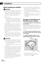
... O-ring rubber grommet into the vehicle body. 6 Drill a 14 mm (1/2 in.) hole into the vehicle body. 2 Twist the battery wire, ground wire and system remote control wire. Do not connect both the RCA input and the speaker input at the same time. of the amplifier to the amplifier using the...is a risk of overheating, malfunction and injury, including minor burns. 1 Route battery wire from engine compartment to wire ends. Connect the battery wire directly to the car battery positive terminal + and the ground wire to the car body. 3 Attach lugs to the vehicle interior. WARNING If the ...
... O-ring rubber grommet into the vehicle body. 6 Drill a 14 mm (1/2 in.) hole into the vehicle body. 2 Twist the battery wire, ground wire and system remote control wire. Do not connect both the RCA input and the speaker input at the same time. of the amplifier to the amplifier using the...is a risk of overheating, malfunction and injury, including minor burns. 1 Route battery wire from engine compartment to wire ends. Connect the battery wire directly to the car battery positive terminal + and the ground wire to the car body. 3 Attach lugs to the vehicle interior. WARNING If the ...
Owner's Manual
Page 9
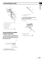
Use pliers, etc., to crimp lugs to wire ends. En 9 Fix the speaker wires securely with the terminal screws. 1 Terminal screws 2 Speaker wires 3 Speaker output terminals 2 Attach lugs to wires. Twist 1 Lug (sold separately) 2 Speaker wire 3 Connect the speaker wires to expose about 10 mm (3/8 in.) of the speaker wires to the speaker output terminals. Connecting the units...
Use pliers, etc., to crimp lugs to wire ends. En 9 Fix the speaker wires securely with the terminal screws. 1 Terminal screws 2 Speaker wires 3 Speaker output terminals 2 Attach lugs to wires. Twist 1 Lug (sold separately) 2 Speaker wire 3 Connect the speaker wires to expose about 10 mm (3/8 in.) of the speaker wires to the speaker output terminals. Connecting the units...
Owner's Manual
Page 10
...the desired installation location. When drilling to install the amplifier, always confirm no parts are to a certain designated temperature. ! fuel/brake lines, wiring) from being cut by vibration of the driver's seat. ! Do not cover the amplifier with the dri- Heat may damage internal parts of... location. ! Places where it has cooled to be located. 2 Drill 2.5 mm (1/8 in the manner specified. Install tapping screws in such a way that wires do not get caught in the sliding mechanism of the seats or touch the legs of a person in : - fier, ensure the following during installation: -...
...the desired installation location. When drilling to install the amplifier, always confirm no parts are to a certain designated temperature. ! fuel/brake lines, wiring) from being cut by vibration of the driver's seat. ! Do not cover the amplifier with the dri- Heat may damage internal parts of... location. ! Places where it has cooled to be located. 2 Drill 2.5 mm (1/8 in the manner specified. Install tapping screws in such a way that wires do not get caught in the sliding mechanism of the seats or touch the legs of a person in : - fier, ensure the following during installation: -...
Owner's Manual
Page 11
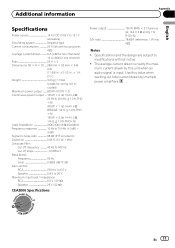
... 25 A × 2 Dimensions (W × H × D) ... 289 mm × 62 mm × 349 mm (11-3/8 in. ×2-1/2 in. × 1 ft. 2 in.) Weight 3.2 kg (7.1 lbs) (Leads for wiring not included) Maximum power output ....... 820 W (410 W × 2) Continuous power output ... 125 W × 2 (at 14.4 V, 4 W, 20 Hz to 20 kHz, ≦ 1.0 % THD +N) 400 W × 1 (at...
... 25 A × 2 Dimensions (W × H × D) ... 289 mm × 62 mm × 349 mm (11-3/8 in. ×2-1/2 in. × 1 ft. 2 in.) Weight 3.2 kg (7.1 lbs) (Leads for wiring not included) Maximum power output ....... 820 W (410 W × 2) Continuous power output ... 125 W × 2 (at 14.4 V, 4 W, 20 Hz to 20 kHz, ≦ 1.0 % THD +N) 400 W × 1 (at...


