
Operating Instructions
Page 6
... 17 Display 17 Remote control 18 04 Getting started Switching on and setting up 20 Making your first recording 22 Using the built-in TV tuner 22 Basic playback 23 Displaying disc information on-screen 25 05 Playback Introduction 27 Using the Disc Navigator to browse the contents of a disc 27...
... 17 Display 17 Remote control 18 04 Getting started Switching on and setting up 20 Making your first recording 22 Using the built-in TV tuner 22 Basic playback 23 Displaying disc information on-screen 25 05 Playback Introduction 27 Using the Disc Navigator to browse the contents of a disc 27...

Operating Instructions
Page 13
...'re available. 13 En This enables you to watch the output from this recorder. 3 Connect the audio/video output of your cable box/satellite tuner to a set of A/V cables. This enables you to watch and record TV channels. 2 Connect the AUDIO and VIDEO OUTPUT jacks on this ... wall outlet Note The diagram shows standard video connections, but you to your TV using a set of audio/video inputs on the cable box/satellite tuner. • Watch one channel while recording another. Always connect each component directly to record scrambled TV channels. A/V IN 1 TV VHF/UHF IN 1 2...
...'re available. 13 En This enables you to watch the output from this recorder. 3 Connect the audio/video output of your cable box/satellite tuner to a set of A/V cables. This enables you to watch and record TV channels. 2 Connect the AUDIO and VIDEO OUTPUT jacks on this ... wall outlet Note The diagram shows standard video connections, but you to your TV using a set of audio/video inputs on the cable box/satellite tuner. • Watch one channel while recording another. Always connect each component directly to record scrambled TV channels. A/V IN 1 TV VHF/UHF IN 1 2...

Operating Instructions
Page 14
... Always connect each component directly to watch and record TV channels. 2 Connect the AUDIO and VIDEO OUTPUT jacks on the cable box/satellite tuner. This enables you to watch one channel and record another. • The diagram shows standard video connections, but you to your cable box/satellite... tuner to the INPUT 1 jacks on your VCR, satellite receiver or cable box. This enables you can alternatively use the S-video or component ...
... Always connect each component directly to watch and record TV channels. 2 Connect the AUDIO and VIDEO OUTPUT jacks on the cable box/satellite tuner. This enables you to watch one channel and record another. • The diagram shows standard video connections, but you to your cable box/satellite... tuner to the INPUT 1 jacks on your VCR, satellite receiver or cable box. This enables you can alternatively use the S-video or component ...

Operating Instructions
Page 18
... recorder is stopped, press to set the recording time in blocks of 30 mins. Press repeatedly to change the channel of the built-in TV tuner. 9 HOME MENU Press to display the Home Menu, from which you can navigate all on -screen menu or display. 11 Playback and recording controls (page... go back one level in multilingual DVD-Video discs. Use CLEAR to clear an entry and start reverse or forward scanning. buttons to change the tuner audio.) SUBTITLE (page 31) Displays/changes the subtitles included in the on -screen displays. or to display the previous or next menu page. / (page 29...
... recorder is stopped, press to set the recording time in blocks of 30 mins. Press repeatedly to change the channel of the built-in TV tuner. 9 HOME MENU Press to display the Home Menu, from which you can navigate all on -screen menu or display. 11 Playback and recording controls (page... go back one level in multilingual DVD-Video discs. Use CLEAR to clear an entry and start reverse or forward scanning. buttons to change the tuner audio.) SUBTITLE (page 31) Displays/changes the subtitles included in the on -screen displays. or to display the previous or next menu page. / (page 29...

Operating Instructions
Page 20
Tuner Antenna Cable Do not set 1 Switch on your TV and set if you don't need the recorder to retune all the channels (if you start ... started Switching on and setting up When you switch the recorder on for the first time, you through setting the clock and the internal TV tuner settings. This takes you can make more detailed settings. • If you don't want to use the Setup Navigator, press (cursor down) to select Cancel...
Tuner Antenna Cable Do not set 1 Switch on your TV and set if you don't need the recorder to retune all the channels (if you start ... started Switching on and setting up When you switch the recorder on for the first time, you through setting the clock and the internal TV tuner settings. This takes you can make more detailed settings. • If you don't want to use the Setup Navigator, press (cursor down) to select Cancel...

Operating Instructions
Page 22
... you want to select TV channels. For example, to a recordable DVD. Playing back your recording The TV program you just recorded should be in TV tuner Changing TV channels There are numbered 2 through 125. 5 Press ì REC to stop playback before the end of the recording, press . 04 Getting started Making...
... you want to select TV channels. For example, to a recordable DVD. Playing back your recording The TV program you just recorded should be in TV tuner Changing TV channels There are numbered 2 through 125. 5 Press ì REC to stop playback before the end of the recording, press . 04 Getting started Making...

Operating Instructions
Page 25
... repeatedly until it disappears. buttons to do this during playback.) When a PBC menu is displayed, use the front panel +/- Note • When playing in TV tuner. 5 Audio mode Shows the broadcast audio mode for recordable DVD, if applicable (VR or Video). Press repeatedly to change the on-screen information. • The...
... repeatedly until it disappears. buttons to do this during playback.) When a PBC menu is displayed, use the front panel +/- Note • When playing in TV tuner. 5 Audio mode Shows the broadcast audio mode for recordable DVD, if applicable (VR or Video). Press repeatedly to change the on-screen information. • The...
Operating Instructions
Page 46
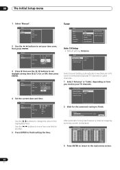
...TV channels. Manual Auto Manual Date Time Time Zone D.S.T. 01 / 01 / 2005 SAT 12 : 00 AM USA Alaska Off Tuner Basic Basic Disc Video Audio Recording Playback Clock Tuner OSD Language Display Remote Control Setup Navigator Auto CH Setup Manual CH Setup Guide CH Setup Auto CH Setup • Default... setting: Antenna Tuner Auto CH Setup Manual CH Setup Guide CH Setup Antenna Cable 3 Press then use the / buttons to terrestrial broadcast TV channels or cable channels....
...TV channels. Manual Auto Manual Date Time Time Zone D.S.T. 01 / 01 / 2005 SAT 12 : 00 AM USA Alaska Off Tuner Basic Basic Disc Video Audio Recording Playback Clock Tuner OSD Language Display Remote Control Setup Navigator Auto CH Setup Manual CH Setup Guide CH Setup Auto CH Setup • Default... setting: Antenna Tuner Auto CH Setup Manual CH Setup Guide CH Setup Antenna Cable 3 Press then use the / buttons to terrestrial broadcast TV channels or cable channels....

Operating Instructions
Page 47
...finished, press ENTER. • You can manually fine tune channels and set channels to skip. Manual CH Setup • Default setting: n/a Tuner Auto CH Setup Manual CH Setup Guide CH Setup Channel Skip AFT Guide CH Setup • Default setting: n/a Guide channels are used by the...manual channel setup screen you want to a station. OSD Language • Default setting: English Basic Basic Disc Video Audio Recording Playback Clock Tuner OSD Language Display Remote Control Setup Navigator This sets the language of the on-screen menus and displays. 2 To return to display the ...
...finished, press ENTER. • You can manually fine tune channels and set channels to skip. Manual CH Setup • Default setting: n/a Tuner Auto CH Setup Manual CH Setup Guide CH Setup Channel Skip AFT Guide CH Setup • Default setting: n/a Guide channels are used by the...manual channel setup screen you want to a station. OSD Language • Default setting: English Basic Basic Disc Video Audio Recording Playback Clock Tuner OSD Language Display Remote Control Setup Navigator This sets the language of the on-screen menus and displays. 2 To return to display the ...

Operating Instructions
Page 48
... the room. 48 En OSD Language OSD Language English There are using more than one Pioneer DVD recorder in standby. Basic Basic Disc Video Audio Recording Playback Clock Tuner OSD Language Display Remote Control Setup Navigator After selecting a new recorder ID, you change ...then pressing ENTER. Setup Navigator • Default setting: n/a Basic Basic Disc Video Audio Recording Playback Clock Tuner OSD Language Display Remote Control Setup Navigator OSD Language Tuner Clock The Setup Navigator appears automatically when you need to switch the front panel display on page 20....
... the room. 48 En OSD Language OSD Language English There are using more than one Pioneer DVD recorder in standby. Basic Basic Disc Video Audio Recording Playback Clock Tuner OSD Language Display Remote Control Setup Navigator After selecting a new recorder ID, you change ...then pressing ENTER. Setup Navigator • Default setting: n/a Basic Basic Disc Video Audio Recording Playback Clock Tuner OSD Language Display Remote Control Setup Navigator OSD Language Tuner Clock The Setup Navigator appears automatically when you need to switch the front panel display on page 20....

Operating Instructions
Page 58
... the TV Screen Size setting (page 55) is correct for copy-once material (page 34). • Two timer programs may have overlapped, in tuner. • When recording to switch the power off, then switch back on the DVD. Timer program doesn't record successfully • When setting the...have failed during recording. cessfully • Check that it (page 8). • discs recorded with ID-1, set the recorder's built-in TV tuner, not the TV's built-in which case only the earlier one will not display or distorted correctly. Connect the recorder directly to use the recorder...
... the TV Screen Size setting (page 55) is correct for copy-once material (page 34). • Two timer programs may have overlapped, in tuner. • When recording to switch the power off, then switch back on the DVD. Timer program doesn't record successfully • When setting the...have failed during recording. cessfully • Check that it (page 8). • discs recorded with ID-1, set the recorder's built-in TV tuner, not the TV's built-in which case only the earlier one will not display or distorted correctly. Connect the recorder directly to use the recorder...
Operating Instructions
Page 65
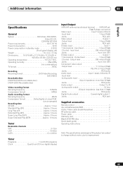
... Approx. 2 hours Long Play (LP Approx. 4 hours Extended Play (EP Approx. 6 hours Super Long Play (SLP Approx. 8 hours Super Extended Play (SEP Approx. 10 hours Tuner Receivable channels VHF 2-13ch UHF 14-69ch CATV C1-C125ch Timer Programs 1 month/32 programs Clock Quartz lock (12-hour digital display) Input/Output VHF...
... Approx. 2 hours Long Play (LP Approx. 4 hours Extended Play (EP Approx. 6 hours Super Long Play (SLP Approx. 8 hours Super Extended Play (SEP Approx. 10 hours Tuner Receivable channels VHF 2-13ch UHF 14-69ch CATV C1-C125ch Timer Programs 1 month/32 programs Clock Quartz lock (12-hour digital display) Input/Output VHF...
Service Manual
Page 6
... Play (EP Approx. 6 hours Super Long Play (SLP Approx. 8 hours Super Extended Play (SEP Approx. 10 hours D Tuner Receivable channels VHF 2-13ch UHF 14-69ch CATV C1-C125ch Timer Programs 1 month/32 programs Clock Quartz lock (12-hour digital ...Vp-p (75Ω) C (color) - B 420 (W) x 69 (H) x 332 (D) mm Operating temperature 5°C to +35°C Operating humidity 5% to improvement. F 6 DVR-231-S 1 2 3 4 1 2 1. SPECIFICATIONS A Specifications General System DVD-Video, DVD-R/RW, Video-CD, CD, CD-R/RW (CD-DA) Power requirements 120 V, 60 Hz ...
... Play (EP Approx. 6 hours Super Long Play (SLP Approx. 8 hours Super Extended Play (SEP Approx. 10 hours D Tuner Receivable channels VHF 2-13ch UHF 14-69ch CATV C1-C125ch Timer Programs 1 month/32 programs Clock Quartz lock (12-hour digital ...Vp-p (75Ω) C (color) - B 420 (W) x 69 (H) x 332 (D) mm Operating temperature 5°C to +35°C Operating humidity 5% to improvement. F 6 DVR-231-S 1 2 3 4 1 2 1. SPECIFICATIONS A Specifications General System DVD-Video, DVD-R/RW, Video-CD, CD, CD-R/RW (CD-DA) Power requirements 120 V, 60 Hz ...

Service Manual
Page 13
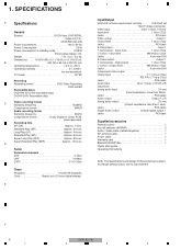
Control Data IC101 PMC002A8 Tuner U-com V201 FL IC201 PT6315 FL Driver CN301(1/2) (40P) SEL.V/Y 29 29 SEL.C 31 31 L SEL.L 25 25 CN2301 (1/2) (40P) • MAIN/SUB CPU • ... LA73054 16 25 YP 14 23 Cb 11 21 Cr 8 28 Y 6 31 C 33 V L OUT 23 SPDIF 40 Tuner U-com POWER B KEYB ASSY REC Key SW PLAY DOWN(-) STOP UP(+) OPEN CN1001 (3P) CN201 (3P) DVR-231-S 5 6 7 JA401 YP Y COMPONENT VIDEO OUT Cb Cb Cr Cr E VOUT YOUT Y COUT C LOUT VIDEO S1 LINE...
Control Data IC101 PMC002A8 Tuner U-com V201 FL IC201 PT6315 FL Driver CN301(1/2) (40P) SEL.V/Y 29 29 SEL.C 31 31 L SEL.L 25 25 CN2301 (1/2) (40P) • MAIN/SUB CPU • ... LA73054 16 25 YP 14 23 Cb 11 21 Cr 8 28 Y 6 31 C 33 V L OUT 23 SPDIF 40 Tuner U-com POWER B KEYB ASSY REC Key SW PLAY DOWN(-) STOP UP(+) OPEN CN1001 (3P) CN201 (3P) DVR-231-S 5 6 7 JA401 YP Y COMPONENT VIDEO OUT Cb Cb Cr Cr E VOUT YOUT Y COUT C LOUT VIDEO S1 LINE...

Service Manual
Page 22
... RXD (AE10) SS_T_TO_M (AC9) ASCK (AC10) SS_M_TO_T VREF_V C1024 1u C1025 1000p GOUT (AC6) BOUT (AA6) C1023 *** YOUT (AA8) ROUT (AA9) COUT (AA10) C 2/2 to&from TUNER-CON (AD1) TX0 5V→3VConv. (AC1) RX0 (2page) (AB18) (AC19) (AD19) (AB19) (AE21) GNDD C 2/2 C 2/2 to VIDEO to A-DAC C 2/2 V+3D C 2/2 V_VENC V+3V PVDD 1R5V to... C1421 1 YF R1451 10k R1452 10k GNDD R1453 SCL 22 SDA R1454 22 R1412 10k R1411 10k*4 R1413 10k JTMRST JTDI JTDO JTMS JTCL EDINT DVR-231-S 2 3 4
... RXD (AE10) SS_T_TO_M (AC9) ASCK (AC10) SS_M_TO_T VREF_V C1024 1u C1025 1000p GOUT (AC6) BOUT (AA6) C1023 *** YOUT (AA8) ROUT (AA9) COUT (AA10) C 2/2 to&from TUNER-CON (AD1) TX0 5V→3VConv. (AC1) RX0 (2page) (AB18) (AC19) (AD19) (AB19) (AE21) GNDD C 2/2 C 2/2 to VIDEO to A-DAC C 2/2 V+3D C 2/2 V_VENC V+3V PVDD 1R5V to... C1421 1 YF R1451 10k R1452 10k GNDD R1453 SCL 22 SDA R1454 22 R1412 10k R1411 10k*4 R1413 10k JTMRST JTDI JTDO JTMS JTCL EDINT DVR-231-S 2 3 4

Service Manual
Page 28
...D GND GND GND 4 CN301 - pin 28 (Y1) (Function : DVD play ) V: 0.5V/div. pin 17 (4V) (Function : Tuner 2 ch) V: 0.5V/div. E GND GND GND 5 CN301 - pin 6 (4L) (Function : Tuner 2 ch) V: 0.5V/div. H: 10µsec/div. 2 CN301 - H: 200µsec/div. GND GND 17 IC402 - H: ... 9 IC401 - H: 200µsec/div. 15 U601 - A A JCKB ASSY 1 IC601 - pin 33 (CVBS) (Function : DVD play ) V: 0.5V/div. F GND GND GND 28 DVR-231-S 1 2 3 4 pin 15 (Y_OUT) (Function : DVD play ) V: 0.5V/div. H: 200µsec/div. 10 IC401 - B 6 CN301 - H: 200µsec/div....
...D GND GND GND 4 CN301 - pin 28 (Y1) (Function : DVD play ) V: 0.5V/div. pin 17 (4V) (Function : Tuner 2 ch) V: 0.5V/div. E GND GND GND 5 CN301 - pin 6 (4L) (Function : Tuner 2 ch) V: 0.5V/div. H: 10µsec/div. 2 CN301 - H: 200µsec/div. GND GND 17 IC402 - H: ... 9 IC401 - H: 200µsec/div. 15 U601 - A A JCKB ASSY 1 IC601 - pin 33 (CVBS) (Function : DVD play ) V: 0.5V/div. F GND GND GND 28 DVR-231-S 1 2 3 4 pin 15 (Y_OUT) (Function : DVD play ) V: 0.5V/div. H: 200µsec/div. 10 IC401 - B 6 CN301 - H: 200µsec/div....

Service Manual
Page 43
... C3106, C3212-C3214 C3216 CCSRCH681J50 CCSRCH8R0D50 CEVW100M16 CEVW101M16 CEVW101M16 KN301 SCREW PLATE VNE1948 KN302-KN306 WRAPPING TERMINAL VNF1084 U601 TV TUNER PACK VXF1059 B KEYB ASSY SWITCHES AND RELAYS S1001-S1006 CAPACITORS C1001 RESISTORS Other Resistors OTHERS 0 HOUSING ASS'Y(3P)...R1265, R1266 R1268, R1269, R1273, R1274 R3810-R3813, R3824 R1281-R1283, R1287 R3208, R3223 RAB4CQ330J RAB4CQ330J RAB4CQ330J RAB4CQ560J RN1/16SC56R0D R3207, R3226 RN1/16SE1502D DVR-231-S 5 6 7 8 A B C D E F 43 Mark No. R524, R525 R316 R304 5 Description Other Resistors OTHERS X101 (15.0 ...
... C3106, C3212-C3214 C3216 CCSRCH681J50 CCSRCH8R0D50 CEVW100M16 CEVW101M16 CEVW101M16 KN301 SCREW PLATE VNE1948 KN302-KN306 WRAPPING TERMINAL VNF1084 U601 TV TUNER PACK VXF1059 B KEYB ASSY SWITCHES AND RELAYS S1001-S1006 CAPACITORS C1001 RESISTORS Other Resistors OTHERS 0 HOUSING ASS'Y(3P)...R1265, R1266 R1268, R1269, R1273, R1274 R3810-R3813, R3824 R1281-R1283, R1287 R3208, R3223 RAB4CQ330J RAB4CQ330J RAB4CQ330J RAB4CQ560J RN1/16SC56R0D R3207, R3226 RN1/16SE1502D DVR-231-S 5 6 7 8 A B C D E F 43 Mark No. R524, R525 R316 R304 5 Description Other Resistors OTHERS X101 (15.0 ...

Service Manual
Page 49
C D E F DVR-231-S 49 5 6 7 8 If you could not download, proceed as follows: A • In a case where downloading was incorrectly terminated while "DL-1" was displayed on the FL ... downloading was incorrectly terminated while "DL-2" was displayed on or when the power is not correctly turned on the FL display The program for the tuner microcomputer will not function correctly.
C D E F DVR-231-S 49 5 6 7 8 If you could not download, proceed as follows: A • In a case where downloading was incorrectly terminated while "DL-1" was displayed on the FL ... downloading was incorrectly terminated while "DL-2" was displayed on or when the power is not correctly turned on the FL display The program for the tuner microcomputer will not function correctly.

Service Manual
Page 55
... with an appropriate DRIVE Assy. for the drive has not been registered. of the tuner microcomputer, Mask or Flash Result of the drive microcomputer is advanced. of the tuner microcomputer, Mask or Flash Result of the combination ckeck with system u-com 5 Information ... : EMMA2RL 7 REGION : 1 8 C 9 FLASH : 32M 1 Model name/destination 2 Version of MAIN LSI 6 Region No. 7 CPRM information (CPRM key No.) F DVR-231-S 55 5 6 7 8 Measures to be taken: Replace with system u-com 4 Information on the built-in drive (Model name, version No., model type, serial No.)...
... with an appropriate DRIVE Assy. for the drive has not been registered. of the tuner microcomputer, Mask or Flash Result of the drive microcomputer is advanced. of the tuner microcomputer, Mask or Flash Result of the combination ckeck with system u-com 5 Information ... : EMMA2RL 7 REGION : 1 8 C 9 FLASH : 32M 1 Model name/destination 2 Version of MAIN LSI 6 Region No. 7 CPRM information (CPRM key No.) F DVR-231-S 55 5 6 7 8 Measures to be taken: Replace with system u-com 4 Information on the built-in drive (Model name, version No., model type, serial No.)...

Service Manual
Page 64
... In Main unit key input #2 19 P84/AN4 KEY3 Analog In Main unit key input #3 20 P85/AN5 AGC Analog In AGC voltage input from tuner 21 P86/AN6 D 22 P87/AN7 BATTERY FUNC Analog In Input for battery voltage checking Analog In 23 P10/SO0 SDET3 I Detection of S tereminal #3 connection... Function No. 1 2 3 4 7.2 IC • The information shown in the schematic diagrams. A List of video selector 39 VSS4 F 40 VDD4 GND − VDD4 − Active 64 DVR-231-S 1 2 3 4
... In Main unit key input #2 19 P84/AN4 KEY3 Analog In Main unit key input #3 20 P85/AN5 AGC Analog In AGC voltage input from tuner 21 P86/AN6 D 22 P87/AN7 BATTERY FUNC Analog In Input for battery voltage checking Analog In 23 P10/SO0 SDET3 I Detection of S tereminal #3 connection... Function No. 1 2 3 4 7.2 IC • The information shown in the schematic diagrams. A List of video selector 39 VSS4 F 40 VDD4 GND − VDD4 − Active 64 DVR-231-S 1 2 3 4