
Digital Proprietary Telephone
Page 1
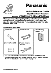
... read this manual carefully before using this product and save this manual for purchasing a Digital Proprietary Telephone (DPT). KX-DT333/KX-DT343/KX-DT346 Thank you for future use. Accessories (included)*1 Handset: 1 Handset Cord: 1 Wall Mounting Adaptor*2: 1 Screws for wall: 2 Telephone Line Cord: 1 *1 For extra orders for the accessories, call toll-free: 1-800-332-5368. *2 This telephone...
... read this manual carefully before using this product and save this manual for purchasing a Digital Proprietary Telephone (DPT). KX-DT333/KX-DT343/KX-DT346 Thank you for future use. Accessories (included)*1 Handset: 1 Handset Cord: 1 Wall Mounting Adaptor*2: 1 Screws for wall: 2 Telephone Line Cord: 1 *1 For extra orders for the accessories, call toll-free: 1-800-332-5368. *2 This telephone...

Digital Proprietary Telephone
Page 12
... the handset cradle when the unit is secured at a high angle. To temporarily place the handset down the handset hook until the operation board is mounted to a wall or set to one level at a time. Operation Board Angle Adjustment Operation Board Angle Adjustment The angle of the operation board can be lowered...
... the handset cradle when the unit is secured at a high angle. To temporarily place the handset down the handset hook until the operation board is mounted to a wall or set to one level at a time. Operation Board Angle Adjustment Operation Board Angle Adjustment The angle of the operation board can be lowered...
Digital Proprietary Telephone
Page 17
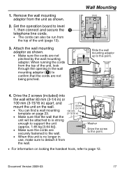
...Document Version 2009-03 17 Remove the wall mounting adaptor from the wall. Wall Mounting Slide the wall mounting adaptor up to page 12. Drive the 2 screws (included) into the wall either 83 mm (3-1/4 in) or 100 mm (3-15/16 in) apart, and mount the unit on the wall. • You can also be ...this point. • For information on page 23. (3-15/16 in) • Make sure that the wall that the cords are not pinched by the wall mounting adaptor. Attach the wall mounting adaptor as shown. 2. When running the cords from the top of the unit, look through the opening ...
...Document Version 2009-03 17 Remove the wall mounting adaptor from the wall. Wall Mounting Slide the wall mounting adaptor up to page 12. Drive the 2 screws (included) into the wall either 83 mm (3-1/4 in) or 100 mm (3-15/16 in) apart, and mount the unit on the wall. • You can also be ...this point. • For information on page 23. (3-15/16 in) • Make sure that the wall that the cords are not pinched by the wall mounting adaptor. Attach the wall mounting adaptor as shown. 2. When running the cords from the top of the unit, look through the opening ...
Digital Proprietary Telephone
Page 23
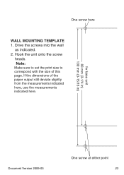
Drive the screws into the wall as indicated. 2. If the dimensions of this page. Note: Make sure to set the print size to correspond with the size of the paper output still deviate slightly from the measurements indicated here, use the measurements indicated here. wall One screw here WALL MOUNTING TEMPLATE 1. for base unit 83 mm (3-1/4 in) 100 mm (3-15/16 in) Document Version 2009-03 One screw at either point 23 Hook the unit onto the screw heads.
Drive the screws into the wall as indicated. 2. If the dimensions of this page. Note: Make sure to set the print size to correspond with the size of the paper output still deviate slightly from the measurements indicated here, use the measurements indicated here. wall One screw here WALL MOUNTING TEMPLATE 1. for base unit 83 mm (3-1/4 in) 100 mm (3-15/16 in) Document Version 2009-03 One screw at either point 23 Hook the unit onto the screw heads.
