

CT32SC13 User Guide
Page 3
... Of Video Games, Computers, Or Other Fixed Image Displays.. 3 Auto Set Up Menu 4 Optional Equipment Connections 5 VCR Connection 5 Front Control Panel 5 Cable Box Connection 5 Digital TV - ENGLISH Table of this manual. 1 l
... Of Video Games, Computers, Or Other Fixed Image Displays.. 3 Auto Set Up Menu 4 Optional Equipment Connections 5 VCR Connection 5 Front Control Panel 5 Cable Box Connection 5 Digital TV - ENGLISH Table of this manual. 1 l

CT32SC13 User Guide
Page 7
... Front Control Panel The front control panel can receive 480i signal only. Separate component color inputs provide luminance and color separation. Procedure • Connect equipment to front Audio/Video input jacks. • Press TV/VIDEO button to view. The on the RF out setting of your television to a... to connect the Panasonic DTV-STB (Digital TV-Set-Top Box) to the back of the cable box. • Using the cable box, tune to the premium cable channel you want to select VIDEO 3 input mode. • Operate optional equipment as instructed in equipment manual. Set-Top Box...
... Front Control Panel The front control panel can receive 480i signal only. Separate component color inputs provide luminance and color separation. Procedure • Connect equipment to front Audio/Video input jacks. • Press TV/VIDEO button to view. The on the RF out setting of your television to a... to connect the Panasonic DTV-STB (Digital TV-Set-Top Box) to the back of the cable box. • Using the cable box, tune to the premium cable channel you want to select VIDEO 3 input mode. • Operate optional equipment as instructed in equipment manual. Set-Top Box...
CT32SC13 User Guide
Page 8
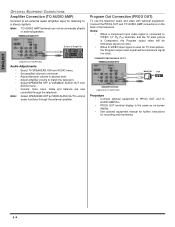
...AUDIO AMP connections on -screen display. • See optional equipment manual for further instructions for TV main picture, the Program output video signal will be luminance signal (no color). External Amplifier CABLES NOT SUPPLIED Audio Adjustments • Select TV SPEAKERS ON from AUDIO menu. • Volume, mute, bass,...to PROG OUT and to VIDEO 1(Y, PB, PR) terminals, and the TV main picture is the same as on the back of the television. Note: TO AUDIO AMP terminals can not be luminance signal (no color). Note: Select SPEAKERS OFF & FIXED AUDIO OUT to externalspeakers. When ...
...AUDIO AMP connections on -screen display. • See optional equipment manual for further instructions for TV main picture, the Program output video signal will be luminance signal (no color). External Amplifier CABLES NOT SUPPLIED Audio Adjustments • Select TV SPEAKERS ON from AUDIO menu. • Volume, mute, bass,...to PROG OUT and to VIDEO 1(Y, PB, PR) terminals, and the TV main picture is the same as on the back of the television. Note: TO AUDIO AMP terminals can not be luminance signal (no color). Note: Select SPEAKERS OFF & FIXED AUDIO OUT to externalspeakers. When ...

CT32SC13 User Guide
Page 15
...select TV (antenna) or CABLE mode depending on black background). r MANUAL ... pressed. r CHAN BANNER - Note: While highlighted, press VOL u to adjust discoloration in Manual Program sub menu. Procedure • Press VOL u to display adjustment menu • Press ...viewer to enter channel numbers in picture. Text may be displayed, up the TV at a time. (It does not block relevant parts of video related information...is used to adjust discoloration of the following modes. • OFF - To manually add or delete channels. CC (CLOSED CAPTIONING) This television contains a built-in...
...select TV (antenna) or CABLE mode depending on black background). r MANUAL ... pressed. r CHAN BANNER - Note: While highlighted, press VOL u to adjust discoloration in Manual Program sub menu. Procedure • Press VOL u to display adjustment menu • Press ...viewer to enter channel numbers in picture. Text may be displayed, up the TV at a time. (It does not block relevant parts of video related information...is used to adjust discoloration of the following modes. • OFF - To manually add or delete channels. CC (CLOSED CAPTIONING) This television contains a built-in...

CT32SC13 User Guide
Page 17
... BALANCE - Procedure • Press VOL u to select desired preset input label (see chart below). ENGLISH CHANNELS CAPTION MANUAL CAPTION - To enter numbers and captions manually. Select when other components are connected. Select STEREO, SAP (Second Audio Program) or MONO. (Use MONO when stereo...keypad to select desired channel (refer to select On or OFF. r AI SOUND - Procedure • Press VOL u to your local TV guide). Procedure • Press VOL u to provide outstanding natural sound. To label video input connections for onscreen display. Sound technology that...
... BALANCE - Procedure • Press VOL u to select desired preset input label (see chart below). ENGLISH CHANNELS CAPTION MANUAL CAPTION - To enter numbers and captions manually. Select when other components are connected. Select STEREO, SAP (Second Audio Program) or MONO. (Use MONO when stereo...keypad to select desired channel (refer to select On or OFF. r AI SOUND - Procedure • Press VOL u to your local TV guide). Procedure • Press VOL u to provide outstanding natural sound. To label video input connections for onscreen display. Sound technology that...

CT32SC13 User Guide
Page 23
TV Programs 17 U.S. Set-Top Box (DTV-STB) or DVD Player Connection 5 F Feature Chart 2 Front Control Panel 5 G Game 16 Geomagnetic Correction 4, 13 I Icon Menu Navigation 12 Icon Menu Operation 13 Idioma/langue 4 Input Label 15 Installation 3 L Lock 16 Lock Set 16 M Manual Caption 15 Manual Program 13 Menu...For Cablebox 11 Codes For DBS 11 Codes For DVD 11 Codes For VCR 11 Color 14 Color Temp 14 Component Codes 10, 11 Congratulations 2 Customer Record 2 IN DEX D Day 14 Digital TV - Movies 17 U.S. TV Programs Rating Chart Description 17 V V-Chip Menu Operation 17 VCR Connection 5 Vivid ...
TV Programs 17 U.S. Set-Top Box (DTV-STB) or DVD Player Connection 5 F Feature Chart 2 Front Control Panel 5 G Game 16 Geomagnetic Correction 4, 13 I Icon Menu Navigation 12 Icon Menu Operation 13 Idioma/langue 4 Input Label 15 Installation 3 L Lock 16 Lock Set 16 M Manual Caption 15 Manual Program 13 Menu...For Cablebox 11 Codes For DBS 11 Codes For DVD 11 Codes For VCR 11 Color 14 Color Temp 14 Component Codes 10, 11 Congratulations 2 Customer Record 2 IN DEX D Day 14 Digital TV - Movies 17 U.S. TV Programs Rating Chart Description 17 V V-Chip Menu Operation 17 VCR Connection 5 Vivid ...

CT32SC13 User Guide
Page 81
Addendum to explain how to exit PICTURE MENU LOCK MODE If you try to adjust PICTURE MENU and the following message is displayed on the TV front panel simultaneously to exit this mode. PICTURE MENU LOCK MODE REFER TO OWNER'S MANUAL TO EXIT THIS MODE Procedure • Press ACTION and CH S buttons on -screen, please follow the procedure below to exit this mode.
Addendum to explain how to exit PICTURE MENU LOCK MODE If you try to adjust PICTURE MENU and the following message is displayed on the TV front panel simultaneously to exit this mode. PICTURE MENU LOCK MODE REFER TO OWNER'S MANUAL TO EXIT THIS MODE Procedure • Press ACTION and CH S buttons on -screen, please follow the procedure below to exit this mode.

Service Manual
Page 1
...Ray Protection Circuit Check& Adjustments 3 EEPROM replacement 4 About lead free solder (PbF) 5 Receiver feature table 6 Board description table 7 TV Location of controls 8 Location of controls (EUR7613Z60 remote) 9 Location of controls (EUR7713010 remote) 10 Dissasembly for service 10.1 Disassembly for ...file:///C|/Documents and Settings/eDOK/ /NA10FL Ch_CT-36SL13G_32SL13G_36SC13G_32SC13G_3653G.htm (1 of 2)04.12.2008 23:59:58 Service Manual TOP NEXT MTNC030729C1 B05 Color Television q CT-36SL13G CT-32SL13G CT-36SC13G CT-32SC13G CT-3653G NA10FL Copyright 2003 Matsushita Electric Corporation of...
...Ray Protection Circuit Check& Adjustments 3 EEPROM replacement 4 About lead free solder (PbF) 5 Receiver feature table 6 Board description table 7 TV Location of controls 8 Location of controls (EUR7613Z60 remote) 9 Location of controls (EUR7713010 remote) 10 Dissasembly for service 10.1 Disassembly for ...file:///C|/Documents and Settings/eDOK/ /NA10FL Ch_CT-36SL13G_32SL13G_36SC13G_32SC13G_3653G.htm (1 of 2)04.12.2008 23:59:58 Service Manual TOP NEXT MTNC030729C1 B05 Color Television q CT-36SL13G CT-32SL13G CT-36SC13G CT-32SC13G CT-3653G NA10FL Copyright 2003 Matsushita Electric Corporation of...
Service Manual
Page 3
http://tsn.pstc.panasonic.com/viewing/NA/CT-36SL13G/SVC/s0000000000.html Service Manual TOP NEXT MTNC030729C1 B05 Color Television q CT-36SL13G CT-32SL13G CT-36SC13G CT-32SC13G CT-3653G NA10FL http://tsn.pstc.panasonic.com/viewing/NA/CT-36SL13G/SVC/s0000000000.html (1 of 2)05.12.2008 0:00:05
http://tsn.pstc.panasonic.com/viewing/NA/CT-36SL13G/SVC/s0000000000.html Service Manual TOP NEXT MTNC030729C1 B05 Color Television q CT-36SL13G CT-32SL13G CT-36SC13G CT-32SC13G CT-3653G NA10FL http://tsn.pstc.panasonic.com/viewing/NA/CT-36SL13G/SVC/s0000000000.html (1 of 2)05.12.2008 0:00:05

Service Manual
Page 7
...procedure check in the high voltage section and the picture tube. TOP PREVIOUS NEXT http://tsn.pstc.panasonic.com/viewing/NA/CT-36SL13G/SVC/s0100000000x.html (3 of prematurecomponent failure. Set the brightness, picture, sharpness and color controls to use an accurate, calibrated high voltage meter. If the upper limit is out of... the high voltage. NOTE It is important to minimum. Horizontal oscillator disable circuit test This test must be 33.0 ± 1.0kV. http://tsn.pstc.panasonic.com/viewing/NA/CT-36SL13G/SVC/s0100000000x.html WARNING The potential source of x ray radiation in the...
...procedure check in the high voltage section and the picture tube. TOP PREVIOUS NEXT http://tsn.pstc.panasonic.com/viewing/NA/CT-36SL13G/SVC/s0100000000x.html (3 of prematurecomponent failure. Set the brightness, picture, sharpness and color controls to use an accurate, calibrated high voltage meter. If the upper limit is out of... the high voltage. NOTE It is important to minimum. Horizontal oscillator disable circuit test This test must be 33.0 ± 1.0kV. http://tsn.pstc.panasonic.com/viewing/NA/CT-36SL13G/SVC/s0100000000x.html WARNING The potential source of x ray radiation in the...
Service Manual
Page 26
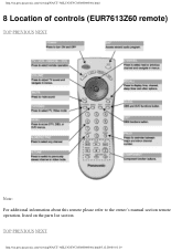
TOP PREVIOUS NEXT http://tsn.pstc.panasonic.com/viewing/NA/CT-36SL13G/SVC/s0800000000x.html05.12.2008 0:01:19 http://tsn.pstc.panasonic.com/viewing/NA/CT-36SL13G/SVC/s0800000000x.html 8 Location of controls (EUR7613Z60 remote) TOP PREVIOUS NEXT Note: For additional information about this remote please refer to the owner's manual section remote operation, listed on the parts list section.
TOP PREVIOUS NEXT http://tsn.pstc.panasonic.com/viewing/NA/CT-36SL13G/SVC/s0800000000x.html05.12.2008 0:01:19 http://tsn.pstc.panasonic.com/viewing/NA/CT-36SL13G/SVC/s0800000000x.html 8 Location of controls (EUR7613Z60 remote) TOP PREVIOUS NEXT Note: For additional information about this remote please refer to the owner's manual section remote operation, listed on the parts list section.
Service Manual
Page 27
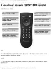
NOTE: CT-3653G includes EUR7613Z60 remote control and an extra remote control with part number EUR7713010 http://tsn.pstc.panasonic.com/viewing/NA/CT-36SL13G/SVC/s0900000000x.html (1 of controls (EUR7713010 remote) TOP PREVIOUS NEXT Note: For additional information about this remote please refer to the owner's manual section remote operation, listed on the parts list section. http://tsn.pstc.panasonic.com/viewing/NA/CT-36SL13G/SVC/s0900000000x.html 9 Location of 2)05.12.2008 0:01:24
NOTE: CT-3653G includes EUR7613Z60 remote control and an extra remote control with part number EUR7713010 http://tsn.pstc.panasonic.com/viewing/NA/CT-36SL13G/SVC/s0900000000x.html (1 of controls (EUR7713010 remote) TOP PREVIOUS NEXT Note: For additional information about this remote please refer to the owner's manual section remote operation, listed on the parts list section. http://tsn.pstc.panasonic.com/viewing/NA/CT-36SL13G/SVC/s0900000000x.html 9 Location of 2)05.12.2008 0:01:24

Service Manual
Page 29
..., please see parts list section for part numbers in this service manual. A-Board - Gently lift the tray and pull out. Disconnect plug connectors; Use same hardware when reassembling the receiver. q 1 screw at each lower corner of TV. cord assembly. q 4 screw by the retainer plate of the... screw at the top edge of 4)05.12.2008 0:01:30 http://tsn.pstc.panasonic.com/viewing/NA/CT-36SL13G/SVC/s1000000000x.html (1 of the receiver. Slide chassis tray out. various models are covered in this manual. q 1 screw by the A.C. release wire ties and holders as required for complete...
..., please see parts list section for part numbers in this service manual. A-Board - Gently lift the tray and pull out. Disconnect plug connectors; Use same hardware when reassembling the receiver. q 1 screw at each lower corner of TV. cord assembly. q 4 screw by the retainer plate of the... screw at the top edge of 4)05.12.2008 0:01:30 http://tsn.pstc.panasonic.com/viewing/NA/CT-36SL13G/SVC/s1000000000x.html (1 of the receiver. Slide chassis tray out. various models are covered in this manual. q 1 screw by the A.C. release wire ties and holders as required for complete...
