User Manual
Page 21
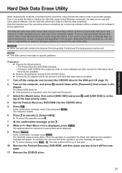
...if you erase the data or initialize the hard disk using this utility. Use the hard disk data erase utility to execute [2. [Erase HDD]]. Note that has been erased using normal Windows commands, the data can be displayed. 9 Press Space. There are also specialized devices that ... Recovery DVD-ROM into the CD/DVD drive. 5 Press F10. Preparation z Prepare the following items: y The Product Recovery DVD-ROM (included) y Panasonic USB CD/DVD drive (optional) (refer to erase highly confidential data, we recommend that you need to recent catalogs and other operational errors...
...if you erase the data or initialize the hard disk using this utility. Use the hard disk data erase utility to execute [2. [Erase HDD]]. Note that has been erased using normal Windows commands, the data can be displayed. 9 Press Space. There are also specialized devices that ... Recovery DVD-ROM into the CD/DVD drive. 5 Press F10. Preparation z Prepare the following items: y The Product Recovery DVD-ROM (included) y Panasonic USB CD/DVD drive (optional) (refer to erase highly confidential data, we recommend that you need to recent catalogs and other operational errors...
User Manual
Page 34
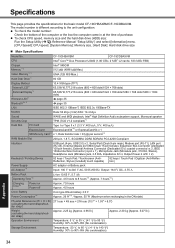
... the unit configuration. Specifications This page provides the specifications for the basic model CF-19CHBAXBM/CF-19CDBAXVM. z To check CPU speed, memory size and the hard disk drive (HDD) size: Run the Setup Utility (Î Reference Manual "Setup Utility") and select [Information] menu. [CPU Speed]: CPU speed...
... the unit configuration. Specifications This page provides the specifications for the basic model CF-19CHBAXBM/CF-19CDBAXVM. z To check CPU speed, memory size and the hard disk drive (HDD) size: Run the Setup Utility (Î Reference Manual "Setup Utility") and select [Information] menu. [CPU Speed]: CPU speed...
Service Manual
Page 7
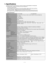
To check CPU speed, memory size and the hard disk drive (HDD) size: Run the Setup Utility ( Reference Manual "Setup Utility") and select [Information] menu. [CPU Speed...Specifications Model No. To check the model number: Check the bottom of purchase. CPU Chipset Memory*2*4 Video Memory*1*3 Hard Disk Drive*4 CF-19FHGAXBM CF-19FDGAXVM Intel® Core™ 2 Duo Processor U7500 (1.06 GHz, 2 MB*1 L2 cache, 533 MHz FSB) Intel®...176;F} Humidity: 30% to the unit configuration. Specifications This page provides the specifications for the basic model CF-19FHGAXBM/CF-19FDGAXVM.
To check CPU speed, memory size and the hard disk drive (HDD) size: Run the Setup Utility ( Reference Manual "Setup Utility") and select [Information] menu. [CPU Speed...Specifications Model No. To check the model number: Check the bottom of purchase. CPU Chipset Memory*2*4 Video Memory*1*3 Hard Disk Drive*4 CF-19FHGAXBM CF-19FDGAXVM Intel® Core™ 2 Duo Processor U7500 (1.06 GHz, 2 MB*1 L2 cache, 533 MHz FSB) Intel®...176;F} Humidity: 30% to the unit configuration. Specifications This page provides the specifications for the basic model CF-19FHGAXBM/CF-19FDGAXVM.
Service Manual
Page 13
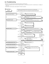
...a troubleshooting. 1. Check Power SW. Replace inverter board. Replace keyboard or main board. Each kind of trouble in operation. Reinstall HDD. Know-how of diagnosis upon occurrence of power input terminal. AC Adaptor/Battery Output voltage NG OK Power lamp NO check YES Inverter...power source). Main board check NG Replace main board OK Make sure of contact of POST NG OK Replace LCD back light. Replace HDD & Reinstall. 4.2. Set cannot be defective. Power lamp fails to troubleshooting: 1. Failure in use. Starts but operates unstably. Replace...
...a troubleshooting. 1. Check Power SW. Replace inverter board. Replace keyboard or main board. Each kind of trouble in operation. Reinstall HDD. Know-how of diagnosis upon occurrence of power input terminal. AC Adaptor/Battery Output voltage NG OK Power lamp NO check YES Inverter...power source). Main board check NG Replace main board OK Make sure of contact of POST NG OK Replace LCD back light. Replace HDD & Reinstall. 4.2. Set cannot be defective. Power lamp fails to troubleshooting: 1. Failure in use. Starts but operates unstably. Replace...
Service Manual
Page 17
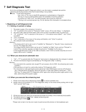
...633;ɹ1.ɹThe power supply of the computer is turned on. ɹɹɹɹ2.ɹ" F2 " is pushed on the screen of "Panasonic" while " press " is displayed. ɹɹɹɹ3.ɹThe setup utility starts and then takes notes of the content of the BIOS ...", the DIAG program cannot perform HDD test This key is for entering DIAG mode. The test of right "Shift" and left "Shift" keys. 3. When you execute an automatic test 1.ɹ"Ctrl" + "F7" is pushed while the "Panasonic" start "PC-Diagnostic utility" again after the computer is made"FULL" display (enhancing test...
...633;ɹ1.ɹThe power supply of the computer is turned on. ɹɹɹɹ2.ɹ" F2 " is pushed on the screen of "Panasonic" while " press " is displayed. ɹɹɹɹ3.ɹThe setup utility starts and then takes notes of the content of the BIOS ...", the DIAG program cannot perform HDD test This key is for entering DIAG mode. The test of right "Shift" and left "Shift" keys. 3. When you execute an automatic test 1.ɹ"Ctrl" + "F7" is pushed while the "Panasonic" start "PC-Diagnostic utility" again after the computer is made"FULL" display (enhancing test...
Service Manual
Page 19
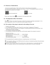
...Close" on the screen while "Pressto enter Setup" is clicked, the computer reactivates automatically. The content of the setup is greatly a difference from HDD according to the setting of "Is the change in order of the tested device ends. 2-2. Standard at test time All devices other than RAM...of PC under the test is a high temperature, it occasionally takes time. çç˙ççThere is returned to the performance of "Panasonic". 3. Push "F10", and on the computer. 2. Start the standard test Do not test Please begin testing clicking if the selection of "The ...
...Close" on the screen while "Pressto enter Setup" is clicked, the computer reactivates automatically. The content of the setup is greatly a difference from HDD according to the setting of "Is the change in order of the tested device ends. 2-2. Standard at test time All devices other than RAM...of PC under the test is a high temperature, it occasionally takes time. çç˙ççThere is returned to the performance of "Panasonic". 3. Push "F10", and on the computer. 2. Start the standard test Do not test Please begin testing clicking if the selection of "The ...
Service Manual
Page 20
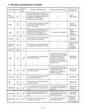
... of a privileged instruction", and DMA, INT, TIMER, and the RTC operation are confirmed. Test Item and Division of trouble Test item Stanard Enhancing Content of HDD is confirmed not to find abnormalityin the wiring between the controller and the connector by confirming the connection of the USB equipment connected with Microsoft.... It is confirmed to be able to HUB with possibility of enhancing test Place with LAN cable. technology". Content of breakdown CPU / Main board RAM HDD MODEM Wireless LAN Sound *5 USB All memory space is tested in the USB controller.
... of a privileged instruction", and DMA, INT, TIMER, and the RTC operation are confirmed. Test Item and Division of trouble Test item Stanard Enhancing Content of HDD is confirmed not to find abnormalityin the wiring between the controller and the connector by confirming the connection of the USB equipment connected with Microsoft.... It is confirmed to be able to HUB with possibility of enhancing test Place with LAN cable. technology". Content of breakdown CPU / Main board RAM HDD MODEM Wireless LAN Sound *5 USB All memory space is tested in the USB controller.
Service Manual
Page 22
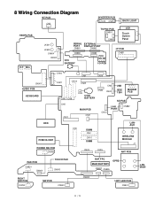
... CN25 CN17 CN8 CN5 CN11 CN3 COIN BATTERY MAIN PCB CN21 CN6 CN24 CN22 USB IEEE 1394 MODEM PCB CN12 SD PCB LAN PORT CN882 HDD PCMCIA UNIT POWER SW PCB CN980 CN4 DIMM CN2 CN10 DIMM CN23 CN15 LANAUX WIRELESS MODULE J1 ANT PCB PAD PCB CN801 CN804 TOUCH PAD...
... CN25 CN17 CN8 CN5 CN11 CN3 COIN BATTERY MAIN PCB CN21 CN6 CN24 CN22 USB IEEE 1394 MODEM PCB CN12 SD PCB LAN PORT CN882 HDD PCMCIA UNIT POWER SW PCB CN980 CN4 DIMM CN2 CN10 DIMM CN23 CN15 LANAUX WIRELESS MODULE J1 ANT PCB PAD PCB CN801 CN804 TOUCH PAD...
Service Manual
Page 23
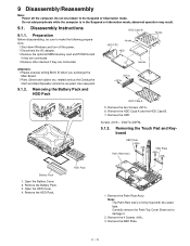
... ï Shut down to damage it. 2. Remove the two Screws . 6. Remove the HDD 2 Screws : DXQT2+D4FNL 9.1.3. Open the HDD Cover. 4. Remove the Palm Rest Ass'y. Remove the KBD Plate. HDD Case B HDD FPC Hooks HDD Hooks Heater Attention: ï Please execute writing BIOS ID when you exchange the Main Board....if they are connected. Do not add peripherals while the computer is firmly fixed with two-sided tape. Removing the Battery Pack and HDD Pack HDD Case A 5. Removing the Touch Pad and Keyboard KBD Plate Palm Rest Ass'y KBD Plate Battery Pack 1. Do not shut down ...
... ï Shut down to damage it. 2. Remove the two Screws . 6. Remove the HDD 2 Screws : DXQT2+D4FNL 9.1.3. Open the HDD Cover. 4. Remove the Palm Rest Ass'y. Remove the KBD Plate. HDD Case B HDD FPC Hooks HDD Hooks Heater Attention: ï Please execute writing BIOS ID when you exchange the Main Board....if they are connected. Do not add peripherals while the computer is firmly fixed with two-sided tape. Removing the Battery Pack and HDD Pack HDD Case A 5. Removing the Touch Pad and Keyboard KBD Plate Palm Rest Ass'y KBD Plate Battery Pack 1. Do not shut down ...
Service Manual
Page 26
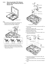
... , and remove the Wireless Module. 13. Removing the Main PCB, Wireless Module, SD PCB, Antenna PCB and Modem PCB Connector(CN8) HDD Connector Guide Connector (CN882) SD PCB Ass'y BAT FPC Ass'y Connector(CN17) Note: This procedure is not necessary if the computer is...2 Screws and the 3 Screws . 4. DIMM Holder Wireless Module Connector(CN3) Modem PCB Coin Battery 11. Remove the 2 Screws , and remove the HDD Connector Guide. 6. Connector(CN15) 5. Disconnect the Cable from the Connector. (CN15) 8. 9.1.9. Remove the 2 Screws. 7. Remove the 3 Screws. 10. Remove...
... , and remove the Wireless Module. 13. Removing the Main PCB, Wireless Module, SD PCB, Antenna PCB and Modem PCB Connector(CN8) HDD Connector Guide Connector (CN882) SD PCB Ass'y BAT FPC Ass'y Connector(CN17) Note: This procedure is not necessary if the computer is...2 Screws and the 3 Screws . 4. DIMM Holder Wireless Module Connector(CN3) Modem PCB Coin Battery 11. Remove the 2 Screws , and remove the HDD Connector Guide. 6. Connector(CN15) 5. Disconnect the Cable from the Connector. (CN15) 8. 9.1.9. Remove the 2 Screws. 7. Remove the 3 Screws. 10. Remove...

Service Manual
Page 30
Remove the Rear Cabinet. (Refer to 7.1.5 Removing the Rear Cabinet) 4. Remove the Battery LID ASS'Y, HDD LID Ass'y and PCMCIA LID Ass'y. Remove the 14 Screws . 2. Screws : DRQT26+D3FKL Screws : DRHM5025YA Remove the 6 Screws . 5. 9.1.19. Removing the Each Cover DC IN ...LID Rubber USB LID Rubber LAN LID Rubber Moden/LAN LID Rubber Battery LID ASS'Y HDD LID ASS'Y Audio LID Rubber USB Back Rubber RGB LID Rubber Serial LID Rubber PCMCIA LID ASS'Y 1. Remove the Modem/LAN LID Rubber, LAN LID...
Remove the Rear Cabinet. (Refer to 7.1.5 Removing the Rear Cabinet) 4. Remove the Battery LID ASS'Y, HDD LID Ass'y and PCMCIA LID Ass'y. Remove the 14 Screws . 2. Screws : DRQT26+D3FKL Screws : DRHM5025YA Remove the 6 Screws . 5. 9.1.19. Removing the Each Cover DC IN ...LID Rubber USB LID Rubber LAN LID Rubber Moden/LAN LID Rubber Battery LID ASS'Y HDD LID ASS'Y Audio LID Rubber USB Back Rubber RGB LID Rubber Serial LID Rubber PCMCIA LID ASS'Y 1. Remove the Modem/LAN LID Rubber, LAN LID...

Service Manual
Page 49
Fix the Modem PCB using the 2 Screws . 6. Fix the Wireless Module using the 2 Screws . 5. HDD Connector Guide Connector (CN882) SD PCB Ass'y BAT FPC Ass'y Connector(CN15) Attach the Cable to the Connector. (CN15) 13. Hook the Flex Cable on ... turn 90 degrees. 11. Connect the cable to the Connector (CN3) and attach the Coin Battery. 4. Fix the DIMM Holder using the 2 Screws . Fix the HDD Connector Guide using the 2 Screws . 7. Fix the SD PCB Ass'y using the 2 Screws . 12. Attach the Cable to the Connector (CN21). 10. Fix the BAT...
Fix the Modem PCB using the 2 Screws . 6. Fix the Wireless Module using the 2 Screws . 5. HDD Connector Guide Connector (CN882) SD PCB Ass'y BAT FPC Ass'y Connector(CN15) Attach the Cable to the Connector. (CN15) 13. Hook the Flex Cable on ... turn 90 degrees. 11. Connect the cable to the Connector (CN3) and attach the Coin Battery. 4. Fix the DIMM Holder using the 2 Screws . Fix the HDD Connector Guide using the 2 Screws . 7. Fix the SD PCB Ass'y using the 2 Screws . 12. Attach the Cable to the Connector (CN21). 10. Fix the BAT...

Service Manual
Page 53
... Fold back Screw Screw Screw 0 1mm Apply the lubricant (sub material) on the center of the FPC. 3mm Audio FPC Ass'y Insert it on the HDD Connector for about 1 second. Thermal Sheet Center of Main Unit Screw Insert and then lock. ■ Assembly of module S4 to make the brown side...
... Fold back Screw Screw Screw 0 1mm Apply the lubricant (sub material) on the center of the FPC. 3mm Audio FPC Ass'y Insert it on the HDD Connector for about 1 second. Thermal Sheet Center of Main Unit Screw Insert and then lock. ■ Assembly of module S4 to make the brown side...

Service Manual
Page 54
Thermal Rubber Screw HDD Connector Guide Screw A Screw SD PCB Ass'y Screw Screw Ensure that the knob is fit to SW when setting. Check S5:Others S3:Sharp Edge Screw DIMM Holder Detail of the HOLDER. DIMM HOLDER Ass'y RF SW Knob Insert the hook Safety Working Screw Insert the FPC CAUTION S1:Insulation S2:Pinching Cables S4:Part No. S2 Put the cables into the hollow space of portion A (assemble the LAN/MODEM HOLDER) LAN/MODEM HOLDER Figure from oblique view Put the claw under the MAIN PCB.
Thermal Rubber Screw HDD Connector Guide Screw A Screw SD PCB Ass'y Screw Screw Ensure that the knob is fit to SW when setting. Check S5:Others S3:Sharp Edge Screw DIMM Holder Detail of the HOLDER. DIMM HOLDER Ass'y RF SW Knob Insert the hook Safety Working Screw Insert the FPC CAUTION S1:Insulation S2:Pinching Cables S4:Part No. S2 Put the cables into the hollow space of portion A (assemble the LAN/MODEM HOLDER) LAN/MODEM HOLDER Figure from oblique view Put the claw under the MAIN PCB.

Service Manual
Page 64
Open the HDD Cover and set the Battery. Open the Battery Cover and set the HDD Pack. 3. 9.2.18. Setting the Battery Pack and the HDD Pack 1. HDD Case B HDD FPC Hooks HDD Hooks Heater 2. Screws : DXQT2+D4FNL HDD Case A 1 3 2 Battery Pack HDD Pack Set the HDD in the HDD Case and fix it using the 2 Screws.
Open the HDD Cover and set the Battery. Open the Battery Cover and set the HDD Pack. 3. 9.2.18. Setting the Battery Pack and the HDD Pack 1. HDD Case B HDD FPC Hooks HDD Hooks Heater 2. Screws : DXQT2+D4FNL HDD Case A 1 3 2 Battery Pack HDD Pack Set the HDD in the HDD Case and fix it using the 2 Screws.

Service Manual
Page 65
... x 4 cm) Heater Insulation Sheet Attach on the inner side of Heater Insulation Sheet 0 0.5mm Note for attachment of the HDD Case A HDD Case Tab HDD Case Lower 0 0.5mm Screw Screw HDD Connector Guard HDD Case Upper Production HDD Damper FPC Connector Insulation Sheet Attach Remove the Release Paper Hook it on the center of the... inside of 1 Details for the Heater top end location 0 1mm Insulation Parts 10 15mm Avoid any stress Insulation Parts Heater Assy 5 1mm Back 5 1mm HDD Connect the Connector Round to make the brown side outside and insert the notch part FPC...
... x 4 cm) Heater Insulation Sheet Attach on the inner side of Heater Insulation Sheet 0 0.5mm Note for attachment of the HDD Case A HDD Case Tab HDD Case Lower 0 0.5mm Screw Screw HDD Connector Guard HDD Case Upper Production HDD Damper FPC Connector Insulation Sheet Attach Remove the Release Paper Hook it on the center of the... inside of 1 Details for the Heater top end location 0 1mm Insulation Parts 10 15mm Avoid any stress Insulation Parts Heater Assy 5 1mm Back 5 1mm HDD Connect the Connector Round to make the brown side outside and insert the notch part FPC...
Service Manual
Page 66
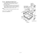
... Serial LID Rubber, the RGB LID Rubber, the Audio LID Rubber and USB Back Rubber using the 6 Screws. 2. 9.2.19. Fix the Battery LID Ass'y, the HDD LID Ass'y, and the PCMCIA LID Ass'y using the 14 Screws. Screws : DRQT26+D3FKL Screw : DRHM5025YA :No.6 :No.5 :No.4 :No.3 DC IN LID Rubber ...USB LID Rubber :No.2 :No.1 LAN LID Rubber Moden/LAN LID Rubber :No.14 3 :No.11 :No.9 :No.10 :No.8 :No.7 Battery LID ASS'Y HDD LID ASS'Y Audio LID Rubber USB Back Rubber RGB LID Rubber Serial LID Rubber PCMCIA LID ASS'Y Set the Rear Cabinet. 3. Assembling the Each Cover 1.
... Serial LID Rubber, the RGB LID Rubber, the Audio LID Rubber and USB Back Rubber using the 6 Screws. 2. 9.2.19. Fix the Battery LID Ass'y, the HDD LID Ass'y, and the PCMCIA LID Ass'y using the 14 Screws. Screws : DRQT26+D3FKL Screw : DRHM5025YA :No.6 :No.5 :No.4 :No.3 DC IN LID Rubber ...USB LID Rubber :No.2 :No.1 LAN LID Rubber Moden/LAN LID Rubber :No.14 3 :No.11 :No.9 :No.10 :No.8 :No.7 Battery LID ASS'Y HDD LID ASS'Y Audio LID Rubber USB Back Rubber RGB LID Rubber Serial LID Rubber PCMCIA LID ASS'Y Set the Rear Cabinet. 3. Assembling the Each Cover 1.
Service Manual
Page 76
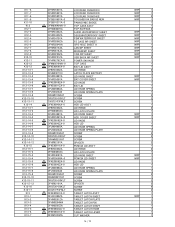
... S DFKE9092YA-0 DFHG1669ZA DFHM0291ZA DFHM0294WA DFHM0295ZA S DFKE0892ZA-0 S DFKE0893YA-0 DFNW1604ZA LCD REAR CUSHION C LCD REAR CUSHION D LCD REAR CUSHION E TOUGHBOOK BADGE NEW PANASONIC BADGE TOP CASE ASS'Y TOP ELEPASS AUDIO WATERPROOF SHEET DSUB WATERPROOF SHEET PSW WATERPROOF SHEET FS CASE WP SHEET GPS HOLE SHEET A LAN WP SHEET...KNOB SPRING PLATE SCREW SCREW SCREW SPACER PCMCIA LID ASS'Y LID HINGE LID LATCH PLATE LID KNOB SHEET PCMCIA LID SHEET LID KNOB HDD LID LID KNOB SPRING LID KNOB SPRING PLATE SCREW SCREW SCREW SPACER SCREW SCREW TABLET LATCH ASS'Y TABLET LATCH SHEET TABLET LATCH ...
... S DFKE9092YA-0 DFHG1669ZA DFHM0291ZA DFHM0294WA DFHM0295ZA S DFKE0892ZA-0 S DFKE0893YA-0 DFNW1604ZA LCD REAR CUSHION C LCD REAR CUSHION D LCD REAR CUSHION E TOUGHBOOK BADGE NEW PANASONIC BADGE TOP CASE ASS'Y TOP ELEPASS AUDIO WATERPROOF SHEET DSUB WATERPROOF SHEET PSW WATERPROOF SHEET FS CASE WP SHEET GPS HOLE SHEET A LAN WP SHEET...KNOB SPRING PLATE SCREW SCREW SCREW SPACER PCMCIA LID ASS'Y LID HINGE LID LATCH PLATE LID KNOB SHEET PCMCIA LID SHEET LID KNOB HDD LID LID KNOB SPRING LID KNOB SPRING PLATE SCREW SCREW SCREW SPACER SCREW SCREW TABLET LATCH ASS'Y TABLET LATCH SHEET TABLET LATCH ...

Service Manual
Page 77
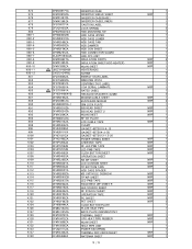
...-0 DFHR6298ZA DFMC0685ZA DFMC0816ZA LATCH KNOB SPRING BOTTOM CASE ASS'Y DIMM LID ASS'Y DIMM LID DIMM LID WP SHEET DU LID ANGLE DU LID WATERPROOF SHEET HDD BOTTOM SHEET DU LID BOTTOM CASE PLATE SPRING GUIDE PIN SCREW SCREW DU CON SPONGE RUBBER HOOT SERIAL LID RUBBER MODEM LID RUBBER USB LID... BAT CON ANGLE PORTRE SHEET CABLE HOLD SHEET KB CNT LID WP SHEET SD BLIND SHEET FS SCREW SHEET POWER SWITCH CABLE SHEET INSULATION SHEET HDD GUIDE DIMM HOLDER RF SW KNOB BAT CON HOLDER FS DUMMY CASE ANT CABLE HOLDER MP GUIDE SHEET PEN DU SPRING INSULATION PARTS DIMM THERMAL...
...-0 DFHR6298ZA DFMC0685ZA DFMC0816ZA LATCH KNOB SPRING BOTTOM CASE ASS'Y DIMM LID ASS'Y DIMM LID DIMM LID WP SHEET DU LID ANGLE DU LID WATERPROOF SHEET HDD BOTTOM SHEET DU LID BOTTOM CASE PLATE SPRING GUIDE PIN SCREW SCREW DU CON SPONGE RUBBER HOOT SERIAL LID RUBBER MODEM LID RUBBER USB LID... BAT CON ANGLE PORTRE SHEET CABLE HOLD SHEET KB CNT LID WP SHEET SD BLIND SHEET FS SCREW SHEET POWER SWITCH CABLE SHEET INSULATION SHEET HDD GUIDE DIMM HOLDER RF SW KNOB BAT CON HOLDER FS DUMMY CASE ANT CABLE HOLDER MP GUIDE SHEET PEN DU SPRING INSULATION PARTS DIMM THERMAL...
Service Manual
Page 78
...SHIELD SHEET INVERTER CASE(BASE) INVERTER CASE(LOWER) CAUTION LABEL LOCK SPRING HDD MOUNTING KIT HDD CASE UPPER HDD CASE LOWER HDD CASE TAB HDD DAMPER HDD CON SHEET HDD CONNECTOR GUARD HDD FPC UNIT INSULATION PARTS INSULATION SHEET(HDD HEATER) WLAN SHEET HEATER(HDD) SCREW ENERGY STAR LABEL WINDOWS VISTA CENTRINO DUO LABEL COA SERIAL LAMINATE ... SHEET AHDESIVE TAPE RF LED PWB TAPE LED PWB TAPE CLICK BUTTON SHEET OPERATION SHEET KB WP SHEET LCD CUSHION SHEET TP BOTTOM TAPE HDD CASE SPACER KB CNT HOLE CUSHION TP WP SHEET LED PWB TAPE PALM REST WP SHEET R LED SYAKOU SHEET RF SYAKOU SHEET OPERATION...
...SHIELD SHEET INVERTER CASE(BASE) INVERTER CASE(LOWER) CAUTION LABEL LOCK SPRING HDD MOUNTING KIT HDD CASE UPPER HDD CASE LOWER HDD CASE TAB HDD DAMPER HDD CON SHEET HDD CONNECTOR GUARD HDD FPC UNIT INSULATION PARTS INSULATION SHEET(HDD HEATER) WLAN SHEET HEATER(HDD) SCREW ENERGY STAR LABEL WINDOWS VISTA CENTRINO DUO LABEL COA SERIAL LAMINATE ... SHEET AHDESIVE TAPE RF LED PWB TAPE LED PWB TAPE CLICK BUTTON SHEET OPERATION SHEET KB WP SHEET LCD CUSHION SHEET TP BOTTOM TAPE HDD CASE SPACER KB CNT HOLE CUSHION TP WP SHEET LED PWB TAPE PALM REST WP SHEET R LED SYAKOU SHEET RF SYAKOU SHEET OPERATION...