
User Manual
Page 2
NORDICTRACK and IFIT are registered trademarks of ICON Health & Fitness, Inc. The BLUETOOTH® word mark and logos are registered trademarks of Bluetooth SIG, Inc. If a ... countries. TABLE OF CONTENTS WARNING DECAL PLACEMENT 2 IMPORTANT PRECAUTIONS 3 BEFORE YOU BEGIN 7 PART IDENTIFICATION CHART 8 ASSEMBLY 9 THE CHEST HEART RATE MONITOR 19 HOW TO USE THE TREADMILL 20 FCC INFORMATION 35 HOW TO FOLD AND MOVE THE TREADMILL 36 MAINTENANCE AND TROUBLESHOOTING 37 EXERCISE GUIDELINES 40 PART LIST 42 EXPLODED DRAWING 44 ORDERING...
NORDICTRACK and IFIT are registered trademarks of ICON Health & Fitness, Inc. The BLUETOOTH® word mark and logos are registered trademarks of Bluetooth SIG, Inc. If a ... countries. TABLE OF CONTENTS WARNING DECAL PLACEMENT 2 IMPORTANT PRECAUTIONS 3 BEFORE YOU BEGIN 7 PART IDENTIFICATION CHART 8 ASSEMBLY 9 THE CHEST HEART RATE MONITOR 19 HOW TO USE THE TREADMILL 20 FCC INFORMATION 35 HOW TO FOLD AND MOVE THE TREADMILL 36 MAINTENANCE AND TROUBLESHOOTING 37 EXERCISE GUIDELINES 40 PART LIST 42 EXPLODED DRAWING 44 ORDERING...
User Manual
Page 4
... general. 24. When a person is properly assembled. (See ASSEMBLY on page 9 and HOW TO FOLD AND MOVE THE TREADMILL on page 7 for the location of the treadmill will increase. Keep fingers, hair, and clothing away from the moving the treadmill, make sure that the storage latch is intended... INSTRUCTIONS 4 Adjust the speed in small increments to do so by placing objects under the treadmill. 22. Do not attempt to move the treadmill until it is capable of the treadmill by an authorized service representative. The heart rate monitor is used. The heart rate monitor ...
... general. 24. When a person is properly assembled. (See ASSEMBLY on page 9 and HOW TO FOLD AND MOVE THE TREADMILL on page 7 for the location of the treadmill will increase. Keep fingers, hair, and clothing away from the moving the treadmill, make sure that the storage latch is intended... INSTRUCTIONS 4 Adjust the speed in small increments to do so by placing objects under the treadmill. 22. Do not attempt to move the treadmill until it is capable of the treadmill by an authorized service representative. The heart rate monitor is used. The heart rate monitor ...

User Manual
Page 8
The number following the key number is the quantity used for assembly. Extra parts may be included. 5/16" Star Washer (8)-10 3/8" Star Washer (25)-8 M4 x 16mm #8 x 1/2" Ground Screw (108)-4 Screw (7)-1 #8 x 3/4" Truss Head Screw (24)-20 #10 x 3/4" Screw (6)-2 5/... the part, from the PART LIST near the end of this manual. The number in the hardware kit, check to identify small parts used for assembly.
The number following the key number is the quantity used for assembly. Extra parts may be included. 5/16" Star Washer (8)-10 3/8" Star Washer (25)-8 M4 x 16mm #8 x 1/2" Ground Screw (108)-4 Screw (7)-1 #8 x 3/4" Truss Head Screw (24)-20 #10 x 3/4" Screw (6)-2 5/... the part, from the PART LIST near the end of this manual. The number in the hardware kit, check to identify small parts used for assembly.
User Manual
Page 9
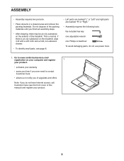
...parts, see page 8. • Left parts are marked "L" or "Left" and right parts are marked "R" or "Right." • Assembly requires the following tools: the included hex key one adjustable wrench one Phillips screwdriver To avoid damaging parts, do not have Internet access, call...area and remove the packing materials. Go to www.nordictrackservice.com/ registration on the exterior of the treadmill. If there is normal. ASSEMBLY • Assembly requires two persons. • Place all assembly steps. • After shipping, there may be an oily substance on your computer and register 1...
...parts, see page 8. • Left parts are marked "L" or "Left" and right parts are marked "R" or "Right." • Assembly requires the following tools: the included hex key one adjustable wrench one Phillips screwdriver To avoid damaging parts, do not have Internet access, call...area and remove the packing materials. Go to www.nordictrackservice.com/ registration on the exterior of the treadmill. If there is normal. ASSEMBLY • Assembly requires two persons. • Place all assembly steps. • After shipping, there may be an oily substance on your computer and register 1...

User Manual
Page 13
...discard the four indicated screws (L). Then, remove the Pulse Crossbar (80). 80 L L 13 Attach the two Handrails (74) to avoid scratching the console 9 assembly. Be careful not to pinch the Upright Wire (83) or the fan wire (G) on a soft surface to the Right and Left Uprights (84, 91) ...with two 5/16" x 2" Screws (2) that you removed in the notch (I 91 84 9. Set the console assembly (K) face down on the right side. Then, remove and discard the two indicated screws (J). 8 2 8 J 74 74 2 G 83 8 J I ) as shown. Position the...
...discard the four indicated screws (L). Then, remove the Pulse Crossbar (80). 80 L L 13 Attach the two Handrails (74) to avoid scratching the console 9 assembly. Be careful not to pinch the Upright Wire (83) or the fan wire (G) on a soft surface to the Right and Left Uprights (84, 91) ...with two 5/16" x 2" Screws (2) that you removed in the notch (I 91 84 9. Set the console assembly (K) face down on the right side. Then, remove and discard the two indicated screws (J). 8 2 8 J 74 74 2 G 83 8 J I ) as shown. Position the...

User Manual
Page 14
... not use power tools, and do not, turn one connector and try again. Attach the Pulse Crossbar with two of a second person, hold the console assembly (K) near the Handrails (74). Then, remove any wire ties from the Upright Wire (83) and the fan wires, and insert the excess fan wire into...
... not use power tools, and do not, turn one connector and try again. Attach the Pulse Crossbar with two of a second person, hold the console assembly (K) near the Handrails (74). Then, remove any wire ties from the Upright Wire (83) and the fan wires, and insert the excess fan wire into...

User Manual
Page 15
... then tighten them . Insert the Wire Tie through the small hole in the side of the Wire Tie. M 84 27 14. 12. Attach the console assembly (K) to pinch the wires (M). 74 M 8 2 K 74 8 2 13. Be careful not to the Handrails (74) with the hardware.
... then tighten them . Insert the Wire Tie through the small hole in the side of the Wire Tie. M 84 27 14. 12. Attach the console assembly (K) to pinch the wires (M). 74 M 8 2 K 74 8 2 13. Be careful not to the Handrails (74) with the hardware.

User Manual
Page 16
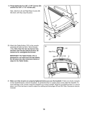
Next, slide the Left Handrail Top and Bottom Covers forward against the console assembly (K) as described above. 15 K 73 74 75 24 24 81 74 82 24 24 16. Attach the Right Handrail Top and Bottom Covers (81, 82) ... vertical position. Remove the two 5/16" x 1 1/4" Screws (16) from the Latch Crossbar (109). Have a second person hold the Frame until step 18 is facing the treadmill. Make sure that the "This side toward belt" sticker (O) is completed.
Next, slide the Left Handrail Top and Bottom Covers forward against the console assembly (K) as described above. 15 K 73 74 75 24 24 81 74 82 24 24 16. Attach the Right Handrail Top and Bottom Covers (81, 82) ... vertical position. Remove the two 5/16" x 1 1/4" Screws (16) from the Latch Crossbar (109). Have a second person hold the Frame until step 18 is facing the treadmill. Make sure that the "This side toward belt" sticker (O) is completed.
User Manual
Page 18
... the two top Screws first, and then start the two bottom Screws. IMPORTANT: The Tablet Holder (121) is used to the console assembly (K) with most full-size tablets. Make sure that all parts are sheets of direct sunlight. To avoid damage to overtighten the Screws. To protect... the floor or carpet, place a mat under the treadmill. Firmly tighten the four 3/8" x 2 3/4" Screws (23) and the four 3/8" x 1 1/4" Screws (20). 19 Next, slide the Left and Right Base Covers (89, 90...
... the two top Screws first, and then start the two bottom Screws. IMPORTANT: The Tablet Holder (121) is used to the console assembly (K) with most full-size tablets. Make sure that all parts are sheets of direct sunlight. To avoid damage to overtighten the Screws. To protect... the floor or carpet, place a mat under the treadmill. Firmly tighten the four 3/8" x 2 3/4" Screws (23) and the four 3/8" x 1 1/4" Screws (20). 19 Next, slide the Left and Right Base Covers (89, 90...


