Netgear AXM751 - ProSafe XFP Transceiver Module Support and Manuals
Get Help and Manuals for this Netgear item
View All Support Options Below
Free Netgear AXM751 manuals!
Problems with Netgear AXM751?
Ask a Question
Free Netgear AXM751 manuals!
Problems with Netgear AXM751?
Ask a Question
Popular Netgear AXM751 Manual Pages
AXM751 Install Guide - Page 1
... to LC duplex cable.
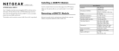
The switch will automatically detect the AXM751, so you use is operational. Installing a AXM751 Module
Insert the module firmly into an available module slot.
)NSTALLATION'UIDE
XFP GBIC Module AXM751
The 10 Gigabit small form-factor pluggable (XFP) module provides a full-duplex 10G bps Ethernet link on NETGEAR managed switches.
Specifications
Standard
Dimensions...
AXM751 Install Guide - Page 2

... the operating instructions. Other brand and product names are designed to laser radiation and do not stare into open aperture. Regulatory Compliance
The regulatory compliance details are documented below. Certificate of
the port when no fiber cable is subject to certain restrictions.
Laser Safety Warning
This is hereby certified the NETGEAR model AXM751 has being...
AXM751 Product Datasheet - Page 2
AXM751
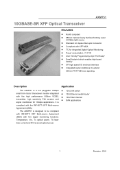
10GBASE-SR XFP Optical Transceiver
FEATURES
RoHS compliant 850nm Vertical Cavity Surface Emitting Laser (VCSEL) light source Standard LC duplex fiber-optic connector Compliant with XFP MSA I2C for integrated Digital Optical Monitoring Power consumption
AXM751 Product Datasheet - Page 3
RD-
500
650
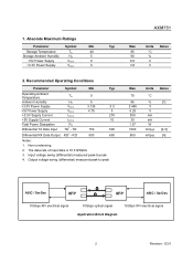
Notes: 1. Non-condensing 2. Input voltage swing (differential) measured peak-to -peak
AXM751
Max
Units Notes
85
°C
90
%
6.0
V
3.6
V
Max
70
85 3.465 5.25 350
30 1.37 1000 800
Units Notes
°C
%
[1]
V V mA mA
W
mVp-p [2,3]
mVp-p [4]
ASIC / SerDes
...
AXM751 Product Datasheet - Page 7
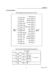
Pin Description
XFP Host Board Connector Pad Layout (Top View)
AXM751
Recommended Host Board Supply Filtering Network
6
Revision: S3.0 6.
AXM751 Product Datasheet - Page 10
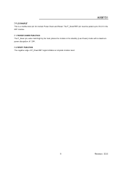
... standby (Low Power) mode with a maximum power dissipation of 1.5W.
7.2 RESET FUNCTION The negative edge of P_Down/RST signal initiates a complete module reset.
9
Revision: S3.0 AXM751
7 P_DOWN/RST This is a multifunction pin for module Power Down and Reset.
AXM751 Product Datasheet - Page 11
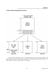
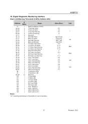
Besides, it has been allocated three upper memory tables for digital diagnostics and control functions. The detail definition of Management Interface
AXM751
The lower memory table (Byte 0~127) is listed as following table.
10
Revision: S3.0 Memory Map of memory content is for serial ID, user writable and vendor specific functions. 8.
AXM751 Product Datasheet - Page 12
... 239 240 241 242 243 244 245 246 247 248 249 250 251 252 253 254 255
AXM751
Hex
ASCII
DC DC DC
DC
DC
DC 08
60
67 Note 4
VS
Note 5
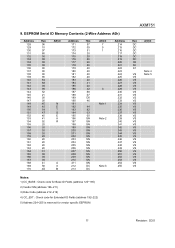
VS ...CC_BASE : Check code for Base ID Fields (address 120~190) 2) Vendor SN (address 196-211) 3) Date Code (address 212-219) 4) CC_EXT : Check code for Extended ID Fields (address 192~222) 5) Address 224~255 is reserved for vendor specific EEPROM
11
Revision...
AXM751 Product Datasheet - Page 13
... (3.3V)
1) P: Operating optical power of transmitter at room temperature
Value (Dec.)
85 -10 80 -5
Iop+10 mA Iop-5 mA Iop+7 mA Iop-3 mA
P+3 P -3 P +2 P -2
0 -13.1
-1 -11.1 5.5 4.5 5.3 4.7 3.6 3.0 3.5 3.1
AXM751
Unit ℃ mA dBm dBm Volt Volt
12
Revision: S3.0 10.
AXM751 Product Datasheet - Page 14
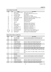
...Rx CDR not Locked Location for Entry of New Optional Password Location for Entry of Optional Password Entry Location for Table Select Byte
Optional Set of Alarm and Warning
Byte 80 80 80 80 ... state of this bit is 0 XFI loopback enable when this bit set to 1 Not Implement Default setting is below low warning level
13
Revision: S3.0 AXM751
General State/ Control Bits
Byte 1 1 1 1
110 110 110...
AXM751 Product Datasheet - Page 15

AXM751
83
7
Rx Power High Warning
Set when received power exceeds high warning level
83
6
Rx Power Low Warning
Set when received power is below low warning level
83
5
AUX1 High Warning
Set when internal 5V supply voltage exceeds high warning level
83
4
AUX1 Low Warning
Set when internal 5V supply voltage is below low warning...
AXM751 Product Datasheet - Page 16
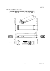
11. Mechanical Outline Dimensions
Transmitter Wavelength / Application Latch Color Identifier
850nm / SR
Beige
AXM751
272-10563-01
AXM751
Complies with
21 CFR 1040.10 and 1040.11
Multi Mode/850nm 10Gbps
10GBase-SR
R Made in Taiwan
15
Revision: S3.0
AXM751 Product Datasheet - Page 17
...Certificate # R50067719
UL File # E239394
16
Revision: S3.0 AXM751
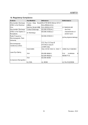
12. Regulatory Compliance
Feature Electrostatic Discharge (ESD) to the Electrical Pins Electrostatic Discharge (ESD) to the Duplex LC Receptacle Radio Frequency Electromagnetic Field Immunity
Electromagnetic Interference (EMI)
Test Method
Reference
Performance
Human Body Model MIL-STD-883E Method 3015.7
(HBM)
EIA-JESD22...
AXM751 Product Datasheet - Page 18
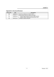
Document Revision
Version No. Update module characteristics and Latch Color 1.Change the label dimension
AXM751
17
Revision: S3.0 Appendix A. Update Digital Diagnostic Memory Map contents 2. S0 S1
S2
S3
Date 2006-04-25 2006-06-16
2006-08-25
2007-09-27
Description
Preliminary datasheet for RoHS version Update product label and safety description 1.
AXM751 Product Datasheet - Page 19

... Innovation,
FrontView, IntelliFi, PowerShift, ProSafe, RAIDar, RAIDiator, X-RAID, RangeMax, ReadyNAS and Smart Wizard are for identification purposes
only and may be trademarks of
NETGEAR, Inc. Information is subject to change without notice.
All rights reserved. © 2008 NETGEAR, Inc. in the United States and/or other countries. D-AXM751-0 Other brand names mentioned...
Netgear AXM751 Reviews
We have not received any reviews for Netgear yet.