Hardware Manual
Page 3
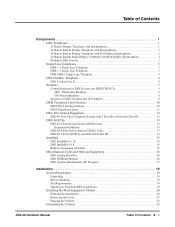
... 5 NEC / Plantronics Headsets 5 GN Netcom Headsets 8 Headsets for DSX Cordless Lite II Telephone 9 DESI Telephone Label System 10 DESI Plus Labeling Software 10 DESI Telephone Labels 11 DSX-40 Common Equipment 12 DSX-40 4x8x2 Key Telephone System with 2 Door Box Ports and Caller-ID 12 DSX-40 PCBs 13 DSX-40 8-Port Digital Station (8ESIU) Card 13 Expansion Guidelines 13 DSX-40 8-Port Analog Station...
... 5 NEC / Plantronics Headsets 5 GN Netcom Headsets 8 Headsets for DSX Cordless Lite II Telephone 9 DESI Telephone Label System 10 DESI Plus Labeling Software 10 DESI Telephone Labels 11 DSX-40 Common Equipment 12 DSX-40 4x8x2 Key Telephone System with 2 Door Box Ports and Caller-ID 12 DSX-40 PCBs 13 DSX-40 8-Port Digital Station (8ESIU) Card 13 Expansion Guidelines 13 DSX-40 8-Port Analog Station...
Hardware Manual
Page 4
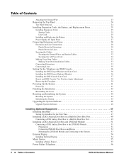
... Wire 23 Removing the Top Panel 24 Top Panel Removal 24 Installing Expansion Cards, the Battery, and Replacement Fuses 25 Installing Expansion Cards 25 Station Cards 25 Line Card 25 Installing and Replacing the Battery 26 Power Supply AC Input Fuses 27 Connecting...DSX Analog Door Box to the 2PGDAD Module 51 Preparation 51 Connecting PGDAD Door Boxes and Relays 52 Mounting the 2PGDAD Module and Connecting to the System 53 External Paging 54 Installing External Paging 54 Music Source 55 Installing a Music Source 55 Power Failure Telephone 56 ii ◆ Table of Contents DSX-40...
... Wire 23 Removing the Top Panel 24 Top Panel Removal 24 Installing Expansion Cards, the Battery, and Replacement Fuses 25 Installing Expansion Cards 25 Station Cards 25 Line Card 25 Installing and Replacing the Battery 26 Power Supply AC Input Fuses 27 Connecting...DSX Analog Door Box to the 2PGDAD Module 51 Preparation 51 Connecting PGDAD Door Boxes and Relays 52 Mounting the 2PGDAD Module and Connecting to the System 53 External Paging 54 Installing External Paging 54 Music Source 55 Installing a Music Source 55 Power Failure Telephone 56 ii ◆ Table of Contents DSX-40...
Hardware Manual
Page 18
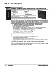
... -the-shelf basic configuration, DSX-40 supports 4 CO (outside) lines with Caller ID, 8 DSX digital keyset extensions, and 2 analog (single line) extensions with power failure. Additionally, the basic DSX-40 provides: • CompactFlash card interface (for IntraMail, software loading, and...2 Total Ports: 40 Ethernet port: Yes (auto sensing) Analog line ports: Built-in: 4 Total: 8 Expansion slots: Station expansion slots: 2 Line expansion slots:1 Audio outputs: 1 Audio inputs: 2 CompactFlash interface: Yes USB connector: Yes DSX-40 is easily expandable by adding station and line PCBs...
... -the-shelf basic configuration, DSX-40 supports 4 CO (outside) lines with Caller ID, 8 DSX digital keyset extensions, and 2 analog (single line) extensions with power failure. Additionally, the basic DSX-40 provides: • CompactFlash card interface (for IntraMail, software loading, and...2 Total Ports: 40 Ethernet port: Yes (auto sensing) Analog line ports: Built-in: 4 Total: 8 Expansion slots: Station expansion slots: 2 Line expansion slots:1 Audio outputs: 1 Audio inputs: 2 CompactFlash interface: Yes USB connector: Yes DSX-40 is easily expandable by adding station and line PCBs...

Hardware Manual
Page 19
... analog stations. Top Position (9-16) 8-Port Digital Card 8-Port Digital Card 8-Port Analog Card DSX-40 Station Card Capacities Middle Position (17-14) 8-Port Digital Card 8-Port Analog Card 8-Port Analog Card Total 24 Digital and 2 Analog 16 Digital and 10 Analog 8 Digital and 18 Analog Tips to remember: • The 8-Port Digital and 8-Port Analog Station Cards use the same expansion slots (upper and middle). DSX-40 Hardware Manual Components ◆ 13 DSX-40...
... analog stations. Top Position (9-16) 8-Port Digital Card 8-Port Digital Card 8-Port Analog Card DSX-40 Station Card Capacities Middle Position (17-14) 8-Port Digital Card 8-Port Analog Card 8-Port Analog Card Total 24 Digital and 2 Analog 16 Digital and 10 Analog 8 Digital and 18 Analog Tips to remember: • The 8-Port Digital and 8-Port Analog Station Cards use the same expansion slots (upper and middle). DSX-40 Hardware Manual Components ◆ 13 DSX-40...

Hardware Manual
Page 22
... have at a delivery entrance, for two DSX Analog Door Boxes. DSX 2PGDAD Module P/N 0891027 Provides connection and relays for two DSX Analog Door Boxes Connects to digital station port At a Glance The DSX 2PGDAD Module provides connection and relays for example. Miscellaneous Cards and Optional Equipment Miscellaneous Cards and Optional Equipment DSX Analog Door Box P/N 922450 DSX-40: • 2 built-in door box...
... have at a delivery entrance, for two DSX Analog Door Boxes. DSX 2PGDAD Module P/N 0891027 Provides connection and relays for two DSX Analog Door Boxes Connects to digital station port At a Glance The DSX 2PGDAD Module provides connection and relays for example. Miscellaneous Cards and Optional Equipment Miscellaneous Cards and Optional Equipment DSX Analog Door Box P/N 922450 DSX-40: • 2 built-in door box...

Hardware Manual
Page 31
... Card 8-Port Analog Card DSX-40 Station Card Capacities Middle Position (17-14) 8-Port Digital Card 8-Port Analog Card 8-Port Analog Card Total 24 Digital and 2 Analog 16 Digital and 10 Analog 8 Digital and 18 Analog Line Card The bottom expansion position is reserved for the 8-port station cards, and you do expand the DSX-40 from 4 lines to 3 Expansion Cards: two for stations and one for lines. Station Cards only Top (Stations 9-16) Middle (Stations...
... Card 8-Port Analog Card DSX-40 Station Card Capacities Middle Position (17-14) 8-Port Digital Card 8-Port Analog Card 8-Port Analog Card Total 24 Digital and 2 Analog 16 Digital and 10 Analog 8 Digital and 18 Analog Line Card The bottom expansion position is reserved for the 8-port station cards, and you do expand the DSX-40 from 4 lines to 3 Expansion Cards: two for stations and one for lines. Station Cards only Top (Stations 9-16) Middle (Stations...
Hardware Manual
Page 32
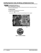
Insert the battery into the battery clips as required. Battery Figure 7: Installing the Battery 1093097 - 6 26 ◆ Installation DSX-40 Hardware Manual OR Go to Installing Expansion Cards (page 25) and install Expansion Cards as shown below. 2. Installing Expansion Cards, the Battery, and Replacement Fuses Installing and Replacing the Battery In the event of commercial AC power failure, the battery provides short-term (14 day) backup of the Real Time Clock and station parameters. To install the battery: 1. Replace and re-secure the top panel.
Insert the battery into the battery clips as required. Battery Figure 7: Installing the Battery 1093097 - 6 26 ◆ Installation DSX-40 Hardware Manual OR Go to Installing Expansion Cards (page 25) and install Expansion Cards as shown below. 2. Installing Expansion Cards, the Battery, and Replacement Fuses Installing and Replacing the Battery In the event of commercial AC power failure, the battery provides short-term (14 day) backup of the Real Time Clock and station parameters. To install the battery: 1. Replace and re-secure the top panel.
Hardware Manual
Page 33
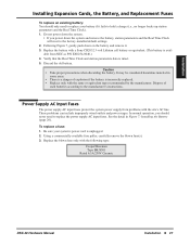
... Cooper/Bussman Type BK/S501 Rated 6.3A/250V Ceramic DSX-40 Hardware Manual Installation ◆ 27 Verify that the Real Time Clock and station parameters data is unplugged. 2. It may be considered ...Power Supply AC Input Fuses The power supply AC input fuses protect the system power supply from NEC as P/N EX0254-0040.) 4. Be sure your battery if it . 3. Following Figure 7, ... to replace the power supply AC input fuses. To replace a fuse: 1. Installation Installing Expansion Cards, the Battery, and Replacement Fuses To replace an existing battery: You should never need to replace...
... Cooper/Bussman Type BK/S501 Rated 6.3A/250V Ceramic DSX-40 Hardware Manual Installation ◆ 27 Verify that the Real Time Clock and station parameters data is unplugged. 2. It may be considered ...Power Supply AC Input Fuses The power supply AC input fuses protect the system power supply from NEC as P/N EX0254-0040.) 4. Be sure your battery if it . 3. Following Figure 7, ... to replace the power supply AC input fuses. To replace a fuse: 1. Installation Installing Expansion Cards, the Battery, and Replacement Fuses To replace an existing battery: You should never need to replace...

Hardware Manual
Page 34
... built-in the top position. STA 13-16 STA 17-20 Second 4 station ports in digital station ports. Using the Installation Cable (P/N 808920) makes it easy to connect the mod jacks to Digital Station and Analog Station Cards as on a BuiltIn Door Box Port (page 49). CO 1-4 CO ... installation cables and 3 associated 66M1-50 connecting blocks. STA 21-24 Second 4 station ports in the middle position STA 25-26 Door 1-2 Built-in the bottom position. 28 ◆ Installation DSX-40 Hardware Manual Four additional lines provided by the line expansion card installed in analog station ports.
... built-in the top position. STA 13-16 STA 17-20 Second 4 station ports in digital station ports. Using the Installation Cable (P/N 808920) makes it easy to connect the mod jacks to Digital Station and Analog Station Cards as on a BuiltIn Door Box Port (page 49). CO 1-4 CO ... installation cables and 3 associated 66M1-50 connecting blocks. STA 21-24 Second 4 station ports in the middle position STA 25-26 Door 1-2 Built-in the bottom position. 28 ◆ Installation DSX-40 Hardware Manual Four additional lines provided by the line expansion card installed in analog station ports.
Hardware Manual
Page 39
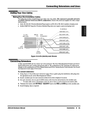
... 25) for Extensions (page 30) as a guide, plug the installation cable plugs into the appropriate jacks on the combination of 8-Port Digital Station and 8-Port Analog Station Cards installed. To CPU Mod Jack Latch faces up 80000 - 18C RJ61X Pin 1 2 3 4 5 6 7 8 Port Designation 4T 3T 2T 1R ...bridging clips as a RJ45 connector wired in your local supplier for each extension, run one-pair 24 AWG station cable from the station block to the modular jack. - DSX-40 Hardware Manual Installation ◆ 33 BLU/WHT leads to the RED and GRN lugs in . Installation Connecting ...
... 25) for Extensions (page 30) as a guide, plug the installation cable plugs into the appropriate jacks on the combination of 8-Port Digital Station and 8-Port Analog Station Cards installed. To CPU Mod Jack Latch faces up 80000 - 18C RJ61X Pin 1 2 3 4 5 6 7 8 Port Designation 4T 3T 2T 1R ...bridging clips as a RJ45 connector wired in your local supplier for each extension, run one-pair 24 AWG station cable from the station block to the modular jack. - DSX-40 Hardware Manual Installation ◆ 33 BLU/WHT leads to the RED and GRN lugs in . Installation Connecting ...

Hardware Manual
Page 72
...DSX Analog Door Box The Analog Door Box is a weather-tight unit, with the main equipment. 5. Near computers, telexes, microwaves, air conditioners, etc. 7. Environmental Requirements Meeting established environmental standards maximizes the life of 2) Music Inputs: 2 Conference Circuits: 8-Port Digital Station Card (Expansion) 8-Port Analog Station Card (Expansion) 4-Port Line Card...not: 1. Specifications DSX-40 System Capacities (Page 2 of the system. Refer to 95% (non-condensing) 66 ◆ Specifications and Parts DSX-40 Hardware Manual Temperature: Humidity:...
...DSX Analog Door Box The Analog Door Box is a weather-tight unit, with the main equipment. 5. Near computers, telexes, microwaves, air conditioners, etc. 7. Environmental Requirements Meeting established environmental standards maximizes the life of 2) Music Inputs: 2 Conference Circuits: 8-Port Digital Station Card (Expansion) 8-Port Analog Station Card (Expansion) 4-Port Line Card...not: 1. Specifications DSX-40 System Capacities (Page 2 of the system. Refer to 95% (non-condensing) 66 ◆ Specifications and Parts DSX-40 Hardware Manual Temperature: Humidity:...

Hardware Manual
Page 73
...voltage 42-103 VAC @ 20 Hz Battery (from telco) 44-56 VDC Output Impedance: Output Level: External Paging 600 Ohm 0 dBr @ 1.0 KHz DSX-40 Hardware Manual Specifications and Parts ◆ 67 Specifications and Parts Specifications Power Supply: Output Power: Input Current: VA: Kwh: BTU... the MDF (between tip Minimum: 36 VDC and ring) Maximum: 44 VDC Minimum operating DC voltage measured at station jack (between tip and ring) 24 VDC Analog Station (SLIU) Card Single Line Telephone Voltages DC voltage measured at the MDF (between tip and ring) On-Hook Idle State Minimum:...
...voltage 42-103 VAC @ 20 Hz Battery (from telco) 44-56 VDC Output Impedance: Output Level: External Paging 600 Ohm 0 dBr @ 1.0 KHz DSX-40 Hardware Manual Specifications and Parts ◆ 67 Specifications and Parts Specifications Power Supply: Output Power: Input Current: VA: Kwh: BTU... the MDF (between tip Minimum: 36 VDC and ring) Maximum: 44 VDC Minimum operating DC voltage measured at station jack (between tip and ring) 24 VDC Analog Station (SLIU) Card Single Line Telephone Voltages DC voltage measured at the MDF (between tip and ring) On-Hook Idle State Minimum:...

Hardware Manual
Page 79
Common Equipment Description DSX-40 DSX-40 Main Equipment Cabinet Additional Common Equipment Installation Cable DSX SMDR Adaptor (requires customer-provided 6-conductor line cord) Cards Description DSX-40 8-Port Digital Station Card (Expansion) 8-Port Analog Station Card (Expansion) 4-Port Line Card with Built-In Caller ID (Expansion) Description IntraMail 8 Port x 16 Hour IntraMail 4 Port x 8 Hour IntraMail Parts List Part Number Part Number 1090001 808920 1091014...
Common Equipment Description DSX-40 DSX-40 Main Equipment Cabinet Additional Common Equipment Installation Cable DSX SMDR Adaptor (requires customer-provided 6-conductor line cord) Cards Description DSX-40 8-Port Digital Station Card (Expansion) 8-Port Analog Station Card (Expansion) 4-Port Line Card with Built-In Caller ID (Expansion) Description IntraMail 8 Port x 16 Hour IntraMail 4 Port x 8 Hour IntraMail Parts List Part Number Part Number 1090001 808920 1091014...