Hardware Manual
Page 4
... Wire 23 Removing the Top Panel 24 Top Panel Removal 24 Installing Expansion Cards, the Battery, and Replacement Fuses 25 Installing Expansion Cards 25 Station Cards 25 Line Card 25 Installing and Replacing the Battery 26 Power Supply AC Input Fuses 27 Connecting...DSX Analog Door Box to the 2PGDAD Module 51 Preparation 51 Connecting PGDAD Door Boxes and Relays 52 Mounting the 2PGDAD Module and Connecting to the System 53 External Paging 54 Installing External Paging 54 Music Source 55 Installing a Music Source 55 Power Failure Telephone 56 ii ◆ Table of Contents DSX-40...
... Wire 23 Removing the Top Panel 24 Top Panel Removal 24 Installing Expansion Cards, the Battery, and Replacement Fuses 25 Installing Expansion Cards 25 Station Cards 25 Line Card 25 Installing and Replacing the Battery 26 Power Supply AC Input Fuses 27 Connecting...DSX Analog Door Box to the 2PGDAD Module 51 Preparation 51 Connecting PGDAD Door Boxes and Relays 52 Mounting the 2PGDAD Module and Connecting to the System 53 External Paging 54 Installing External Paging 54 Music Source 55 Installing a Music Source 55 Power Failure Telephone 56 ii ◆ Table of Contents DSX-40...
Hardware Manual
Page 8
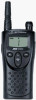
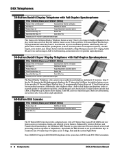
... features a large 9 line-by-24 character backlit alphanumeric display with Hotline keys to Page, Park and the system Night Mode Note: DSX80/160 supports DS1000/2000 telephones if the system has a DSTU Card (P/N 80021A) installed. 2 ◆ Components DSX-40 Hardware Manual DSX Telephones 34-Button Backlit Display Telephone with Full-Duplex Speakerphone At a Glance P/Ns...
... features a large 9 line-by-24 character backlit alphanumeric display with Hotline keys to Page, Park and the system Night Mode Note: DSX80/160 supports DS1000/2000 telephones if the system has a DSTU Card (P/N 80021A) installed. 2 ◆ Components DSX-40 Hardware Manual DSX Telephones 34-Button Backlit Display Telephone with Full-Duplex Speakerphone At a Glance P/Ns...
Hardware Manual
Page 18
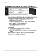
... basic configuration, DSX-40 supports 4 CO (outside) lines with Caller ID, 8 DSX digital keyset extensions, and 2 analog (single line) extensions with power failure. It does not provide high voltage Message Waiting. See DSX-40 PCBs (page 13) for a few seconds while a software update CompactFlash card is installed). 2. DSX-40 Common Equipment DSX-40 Common Equipment DSX-40 4x8x2 Key Telephone System with...
... basic configuration, DSX-40 supports 4 CO (outside) lines with Caller ID, 8 DSX digital keyset extensions, and 2 analog (single line) extensions with power failure. It does not provide high voltage Message Waiting. See DSX-40 PCBs (page 13) for a few seconds while a software update CompactFlash card is installed). 2. DSX-40 Common Equipment DSX-40 Common Equipment DSX-40 4x8x2 Key Telephone System with...
Hardware Manual
Page 25
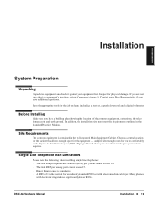
...for you have significantly lower RENs. DSX-40 Hardware Manual Installation ◆ 19 Contact your Sales Representative if you to comfortably work. Figure 1: Installation Layout, DSX-40 (page 20) and shows you about a component's function, review Components (page 1). Have the appropriate tools for an industry ...❥ The total Ringer Equivalence Number (REN) per system cannot exceed 10. ❥ The total REN per analog port cannot exceed 5. ❥ Ringer Equivalence is contained in the Standard Practices Manual. Many phones with electromechanical ringer. Inspect for the...
...for you have significantly lower RENs. DSX-40 Hardware Manual Installation ◆ 19 Contact your Sales Representative if you to comfortably work. Figure 1: Installation Layout, DSX-40 (page 20) and shows you about a component's function, review Components (page 1). Have the appropriate tools for an industry ...❥ The total Ringer Equivalence Number (REN) per system cannot exceed 10. ❥ The total REN per analog port cannot exceed 5. ❥ Ringer Equivalence is contained in the Standard Practices Manual. Many phones with electromechanical ringer. Inspect for the...
Hardware Manual
Page 32
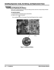
OR Go to Installing Expansion Cards (page 25) and install Expansion Cards as shown below. 2. Battery Figure 7: Installing the Battery 1093097 - 6 26 ◆ Installation DSX-40 Hardware Manual Replace and re-secure the top panel. Insert the battery into the battery clips as required. To install the battery: 1. Installing Expansion Cards, the Battery, and Replacement Fuses Installing and Replacing the Battery In the event of commercial AC power failure, the battery provides short-term (14 day) backup of the Real Time Clock and station parameters.
OR Go to Installing Expansion Cards (page 25) and install Expansion Cards as shown below. 2. Battery Figure 7: Installing the Battery 1093097 - 6 26 ◆ Installation DSX-40 Hardware Manual Replace and re-secure the top panel. Insert the battery into the battery clips as required. To install the battery: 1. Installing Expansion Cards, the Battery, and Replacement Fuses Installing and Replacing the Battery In the event of commercial AC power failure, the battery provides short-term (14 day) backup of the Real Time Clock and station parameters.
Hardware Manual
Page 33
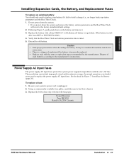
...discarding the battery. It may be considered hazardous material in Figure 7: Installing the Battery (page 26). Do not power down the system. • If you should only need ... the battery with the following type: Cooper/Bussman Type BK/S501 Rated 6.3A/250V Ceramic DSX-40 Hardware Manual Installation ◆ 27 Using a commercially-available fuse puller, carefully remove the blown...power supply AC input fuses protect the system power supply from NEC as P/N EX0254-0040.) 4. Installation Installing Expansion Cards, the Battery, and Replacement Fuses To replace an existing battery...
...discarding the battery. It may be considered hazardous material in Figure 7: Installing the Battery (page 26). Do not power down the system. • If you should only need ... the battery with the following type: Cooper/Bussman Type BK/S501 Rated 6.3A/250V Ceramic DSX-40 Hardware Manual Installation ◆ 27 Using a commercially-available fuse puller, carefully remove the blown...power supply AC input fuses protect the system power supply from NEC as P/N EX0254-0040.) 4. Installation Installing Expansion Cards, the Battery, and Replacement Fuses To replace an existing battery...

Hardware Manual
Page 34
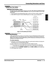
... These cables have six 8-pin modular jacks on one end and are unterminated on a BuiltIn Door Box Port (page 49). See Installing a DSX Analog Door Box on the other. Connecting Extensions and Lines Connecting Extensions and Lines Extension and Line Connections Important Install station... STA 5-8 Second 4 built-in the bottom position. 28 ◆ Installation DSX-40 Hardware Manual Using the Installation Cable (P/N 808920) makes it easy to connect the mod jacks to Digital Station and Analog Station Cards as on-premises extensions only. CO 1-4 CO 5-8 Four built-in digital ...
... These cables have six 8-pin modular jacks on one end and are unterminated on a BuiltIn Door Box Port (page 49). See Installing a DSX Analog Door Box on the other. Connecting Extensions and Lines Connecting Extensions and Lines Extension and Line Connections Important Install station... STA 5-8 Second 4 built-in the bottom position. 28 ◆ Installation DSX-40 Hardware Manual Using the Installation Cable (P/N 808920) makes it easy to connect the mod jacks to Digital Station and Analog Station Cards as on-premises extensions only. CO 1-4 CO 5-8 Four built-in digital ...

Hardware Manual
Page 36
... Extensions To punch down the Installation Cable in standard color-code order. 1093097 - 9 To make your own cables, see Making Your Own Cables (page 33). 1 2 3 4 5 6 8 1 RJ61X Plug Extensions 300-323 Shown 25-PAIR CABLE BLOCK COLOR RJ61X TERM CODE FUNCTION RJ61X 1... 35 YEL-GRN 317 T 3 36 GRN-YEL 317 R 5 37 YEL-BRN 318 T 6 2 38 BRN-YEL 318 R 7 39 YEL-SLT 319 T 1 40 SLT-YEL 319 R 8 41 VIO-BLU 320 T 5 42 BLU-VIO 320 R 4 43 VIO-ORN 321 T 3 44 ORN-VIO 321 R 6 45 VIO...: 1. For each 66M1-50 block, punch down the cables for Extensions DSX-40 Hardware Manual
... Extensions To punch down the Installation Cable in standard color-code order. 1093097 - 9 To make your own cables, see Making Your Own Cables (page 33). 1 2 3 4 5 6 8 1 RJ61X Plug Extensions 300-323 Shown 25-PAIR CABLE BLOCK COLOR RJ61X TERM CODE FUNCTION RJ61X 1... 35 YEL-GRN 317 T 3 36 GRN-YEL 317 R 5 37 YEL-BRN 318 T 6 2 38 BRN-YEL 318 R 7 39 YEL-SLT 319 T 1 40 SLT-YEL 319 R 8 41 VIO-BLU 320 T 5 42 BLU-VIO 320 R 4 43 VIO-ORN 321 T 3 44 ORN-VIO 321 R 6 45 VIO...: 1. For each 66M1-50 block, punch down the cables for Extensions DSX-40 Hardware Manual

Hardware Manual
Page 37
To make your own cables, see Making Your Own Cables (page 33). 1 2 8 1 RJ61X Plug Lines 1-8 25-PAIR CABLE BLOCK COLOR RJ61X TERM CODE FUNCTION 1 WHT-BLU 1 T 2 BLU-WHT 1 R 3 WHT-ORN 2 T 1 4 ORN-WHT 2 R 5 WHT-GRN 3 T 6 GRN-...-YEL NC 33 YEL-ORN 34 ORN-YEL 35 YEL-GRN 36 GRN-YEL 37 YEL-BRN 38 BRN-YEL 39 YEL-SLT 40 SLT-YEL 41 VIO-BLU 42 BLU-VIO 43 VIO-ORN 44 ORN-VIO 45 VIO-GRN 46 GRN-VIO 47 VIO-BRN... punch down the Installation Cable in standard color-code order. For each 66M1-50 block, punch down the cable for Lines DSX-40 Hardware Manual Installation ◆ 31
To make your own cables, see Making Your Own Cables (page 33). 1 2 8 1 RJ61X Plug Lines 1-8 25-PAIR CABLE BLOCK COLOR RJ61X TERM CODE FUNCTION 1 WHT-BLU 1 T 2 BLU-WHT 1 R 3 WHT-ORN 2 T 1 4 ORN-WHT 2 R 5 WHT-GRN 3 T 6 GRN-...-YEL NC 33 YEL-ORN 34 ORN-YEL 35 YEL-GRN 36 GRN-YEL 37 YEL-BRN 38 BRN-YEL 39 YEL-SLT 40 SLT-YEL 41 VIO-BLU 42 BLU-VIO 43 VIO-ORN 44 ORN-VIO 45 VIO-GRN 46 GRN-VIO 47 VIO-BRN... punch down the Installation Cable in standard color-code order. For each 66M1-50 block, punch down the cable for Lines DSX-40 Hardware Manual Installation ◆ 31
Hardware Manual
Page 39
... Figure 13: 8-Pin (RJ61X) Jack Pinouts Connecting Extensions A fully expanded DSX-40 can connect up to as a RJ45 connector wired in an RJ61X configuration. Using Figure 9: Punch Down for Extensions (page 30) as required. Terminate the station cable WHT/BLU - To connect ... require a special crimping tool). The configuration of 8-Port Digital Station and 8-Port Analog Station Cards installed. DSX-40 Hardware Manual Installation ◆ 33 See Installing Expansion Cards (page 25) for each extension, run one-pair 24 AWG station cable from the station block to...
... Figure 13: 8-Pin (RJ61X) Jack Pinouts Connecting Extensions A fully expanded DSX-40 can connect up to as a RJ45 connector wired in an RJ61X configuration. Using Figure 9: Punch Down for Extensions (page 30) as required. Terminate the station cable WHT/BLU - To connect ... require a special crimping tool). The configuration of 8-Port Digital Station and 8-Port Analog Station Cards installed. DSX-40 Hardware Manual Installation ◆ 33 See Installing Expansion Cards (page 25) for each extension, run one-pair 24 AWG station cable from the station block to...
Hardware Manual
Page 41
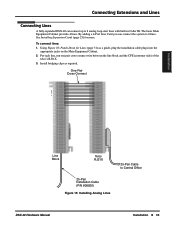
... Cards (page 25) for Lines (page 31) as required. Install bridging clips as a guide, plug the installation cable plugs into the appropriate jacks on the Main Equipment Cabinet. 2. Connecting Extensions and Lines Connecting Lines A fully expanded DSX-40 can connect the system to 8 analog ... Connect Installation 1093097 - 13 Line Block Telco RJ21X 25-Pair Installation Cable (P/N 808920) Figure 15: Installing Analog Lines 25-Pair Cable to Central Office DSX-40 Hardware Manual Installation ◆ 35 To connect lines: 1. The basic Main Equipment Cabinet provides 4 lines....
... Cards (page 25) for Lines (page 31) as required. Install bridging clips as a guide, plug the installation cable plugs into the appropriate jacks on the Main Equipment Cabinet. 2. Connecting Extensions and Lines Connecting Lines A fully expanded DSX-40 can connect the system to 8 analog ... Connect Installation 1093097 - 13 Line Block Telco RJ21X 25-Pair Installation Cable (P/N 808920) Figure 15: Installing Analog Lines 25-Pair Cable to Central Office DSX-40 Hardware Manual Installation ◆ 35 To connect lines: 1. The basic Main Equipment Cabinet provides 4 lines....

Hardware Manual
Page 55
...and changes easier.) 4. Using Figure 30: Connecting to the Built-In Analog Door Box Ports (page 50) as a guide, on a Built-In Door Box Port Connecting a DSX Analog Door Box to a Built-In Door Box Port Do not connect a DSX Analog Door Box to a digital station port. Plug the appropriate installation cable ... 325). Relay Contact Specifications Important! Terminate the station cable WHT/BLU - BLU/WHT leads to the RED and GRN lugs in DSX-40 analog door box ports and relays: 1. You can use this relay to release an electric strike on the Main Equipment Cabinet. 3. Be sure the...
...and changes easier.) 4. Using Figure 30: Connecting to the Built-In Analog Door Box Ports (page 50) as a guide, on a Built-In Door Box Port Connecting a DSX Analog Door Box to a Built-In Door Box Port Do not connect a DSX Analog Door Box to a digital station port. Plug the appropriate installation cable ... 325). Relay Contact Specifications Important! Terminate the station cable WHT/BLU - BLU/WHT leads to the RED and GRN lugs in DSX-40 analog door box ports and relays: 1. You can use this relay to release an electric strike on the Main Equipment Cabinet. 3. Be sure the...

Hardware Manual
Page 56
Installing a DSX Analog Door Box on a Built-In Door Box Port 1093097 - 27 25-PAIR CABLE BLOCK COLOR RJ61X TERM CODE FUNCTION 1 WHT-BLU 324 T 2 BLU-WHT 324 R 3 ... Modular Jack Optional YEL BLU-WHT BLK WHT-BLU RED GRN Door 1T Door 1R Figure 30: Connecting to the Built-In Analog Door Box Ports You can also connect a DSX Analog Door Box to a 2PGDAD Module. See Installing a DSX Analog Door Box and 2PGDAD Module (page 51) for more. 50 ◆ Optional Equipment DSX-40 Hardware Manual
Installing a DSX Analog Door Box on a Built-In Door Box Port 1093097 - 27 25-PAIR CABLE BLOCK COLOR RJ61X TERM CODE FUNCTION 1 WHT-BLU 324 T 2 BLU-WHT 324 R 3 ... Modular Jack Optional YEL BLU-WHT BLK WHT-BLU RED GRN Door 1T Door 1R Figure 30: Connecting to the Built-In Analog Door Box Ports You can also connect a DSX Analog Door Box to a 2PGDAD Module. See Installing a DSX Analog Door Box and 2PGDAD Module (page 51) for more. 50 ◆ Optional Equipment DSX-40 Hardware Manual

Hardware Manual
Page 60
...;er: 1. Plug the other . 2. External Paging External Paging Installing External Paging The Main Equipment Cabinet provides an External Paging output. Plug the mono audio minijack into the paging amplfier. 1093097 - 24 Audio Out Audio Cable To customer-provided paging amplifier Figure 34: Connecting External Paging 54 ◆ Optional Equipment DSX-40 Hardware Manual Obtain an audio cable...
...;er: 1. Plug the other . 2. External Paging External Paging Installing External Paging The Main Equipment Cabinet provides an External Paging output. Plug the mono audio minijack into the paging amplfier. 1093097 - 24 Audio Out Audio Cable To customer-provided paging amplifier Figure 34: Connecting External Paging 54 ◆ Optional Equipment DSX-40 Hardware Manual Obtain an audio cable...

Hardware Manual
Page 62
For more on the line you connected. - When power fails: ❥ Analog extension 324 (station 25) automatically cuts through to line 1. ❥ Analog extension 325 (station 26) automatically cuts through to line 2. To test the Power Failure Telephone: 1. At the ... dial tone on connecting extensions, see Connecting Extensions and Lines (page 28). Analog stations 25 and 26 (extensions 324 and 325) are the permanent power failure extensions. Place a test call. 56 ◆ Optional Equipment DSX-40 Hardware Manual Connect the power failure telephone. 2. Power Failure Telephone...
For more on the line you connected. - When power fails: ❥ Analog extension 324 (station 25) automatically cuts through to line 1. ❥ Analog extension 325 (station 26) automatically cuts through to line 2. To test the Power Failure Telephone: 1. At the ... dial tone on connecting extensions, see Connecting Extensions and Lines (page 28). Analog stations 25 and 26 (extensions 324 and 325) are the permanent power failure extensions. Place a test call. 56 ◆ Optional Equipment DSX-40 Hardware Manual Connect the power failure telephone. 2. Power Failure Telephone...

Hardware Manual
Page 71
... Plugs into a digital station port DSX Analog Door Box Ports (Built-In) 2 DSX Analog Door Boxes (With 2PGDAD Modules) Power Failure Telephones: Internal Paging Zones: External Page Audio Output: Max. Specifications and Parts Specifications and Parts Specifications Specifications DSX Telephone System Specifications DSX-40 System Capacities (Page 1 of available digital station ports...
... Plugs into a digital station port DSX Analog Door Box Ports (Built-In) 2 DSX Analog Door Boxes (With 2PGDAD Modules) Power Failure Telephones: Internal Paging Zones: External Page Audio Output: Max. Specifications and Parts Specifications and Parts Specifications Specifications DSX Telephone System Specifications DSX-40 System Capacities (Page 1 of available digital station ports...

Hardware Manual
Page 72
...) 8-Port Analog Station Card (Expansion) 4-Port Line Card with Built-In Caller ID (Expansion) 32 Conference circuits dynamically allocated, with 8 parties max per Conference. Temperature: Humidity: -20 to 60oC (-4 to 104oF) 10 to the Standard Practices Manual for further information. In places where shocks or vibrations are produced. 3. Specifications DSX-40 System Capacities (Page...
...) 8-Port Analog Station Card (Expansion) 4-Port Line Card with Built-In Caller ID (Expansion) 32 Conference circuits dynamically allocated, with 8 parties max per Conference. Temperature: Humidity: -20 to 60oC (-4 to 104oF) 10 to the Standard Practices Manual for further information. In places where shocks or vibrations are produced. 3. Specifications DSX-40 System Capacities (Page...

Hardware Manual
Page 73
... Specifications Power Supply: Output Power: Input Current: VA: Kwh: BTU: Grounding Requirements: DSX-40 Electrical Specifications 120 VAC + 10% @ 50-60 Hz 83 Watts @ 100% full...Maximum: 44 VDC Minimum operating DC voltage measured at station jack (between tip and ring) 24 VDC Analog Station (SLIU) Card Single Line Telephone Voltages DC voltage measured at the MDF (between tip and ring) On-Hook Idle State... Battery (from telco) 44-56 VDC Output Impedance: Output Level: External Paging 600 Ohm 0 dBr @ 1.0 KHz DSX-40 Hardware Manual Specifications and Parts ◆ 67
... Specifications Power Supply: Output Power: Input Current: VA: Kwh: BTU: Grounding Requirements: DSX-40 Electrical Specifications 120 VAC + 10% @ 50-60 Hz 83 Watts @ 100% full...Maximum: 44 VDC Minimum operating DC voltage measured at station jack (between tip and ring) 24 VDC Analog Station (SLIU) Card Single Line Telephone Voltages DC voltage measured at the MDF (between tip and ring) On-Hook Idle State... Battery (from telco) 44-56 VDC Output Impedance: Output Level: External Paging 600 Ohm 0 dBr @ 1.0 KHz DSX-40 Hardware Manual Specifications and Parts ◆ 67

Hardware Manual
Page 79
Common Equipment Description DSX-40 DSX-40 Main Equipment Cabinet Additional Common Equipment Installation Cable DSX SMDR Adaptor (requires customer-provided 6-conductor line cord) Cards Description DSX-40 8-Port Digital Station Card (Expansion) 8-Port Analog Station Card (Expansion) 4-Port Line Card with Built-In Caller ID (Expansion) Description IntraMail 8 Port x 16 Hour IntraMail 4 Port x 8 Hour IntraMail Parts List Part Number Part Number 1090001...
Common Equipment Description DSX-40 DSX-40 Main Equipment Cabinet Additional Common Equipment Installation Cable DSX SMDR Adaptor (requires customer-provided 6-conductor line cord) Cards Description DSX-40 8-Port Digital Station Card (Expansion) 8-Port Analog Station Card (Expansion) 4-Port Line Card with Built-In Caller ID (Expansion) Description IntraMail 8 Port x 16 Hour IntraMail 4 Port x 8 Hour IntraMail Parts List Part Number Part Number 1090001...

Programming Guide
Page 15
... UCD Group: INTERCOM + *5 + 4 (to reinstall) or 6 (to remove) + SPEAKER Secure your telephone to coworkers that can work closely together. Features Features DSX Programmer's Quick Reference - Features (Page 7 of 19) Feature Do Not Disturb Operation: Do Not Disturb Override Description Programming An extension user can 't readily get to their phones. 2102... (0-3) 2PGDAD Module Door Box Setup 1203-01: Secondary Station Port Assignment Plug 2PGDAD into digital station port 1605-03: Door Relay Unlock Timer DSX-40 "Built-In" Door Box Setup 2101-06: Door Relay Assignment (Door 1 = 326,.
... UCD Group: INTERCOM + *5 + 4 (to reinstall) or 6 (to remove) + SPEAKER Secure your telephone to coworkers that can work closely together. Features Features DSX Programmer's Quick Reference - Features (Page 7 of 19) Feature Do Not Disturb Operation: Do Not Disturb Override Description Programming An extension user can 't readily get to their phones. 2102... (0-3) 2PGDAD Module Door Box Setup 1203-01: Secondary Station Port Assignment Plug 2PGDAD into digital station port 1605-03: Door Relay Unlock Timer DSX-40 "Built-In" Door Box Setup 2101-06: Door Relay Assignment (Door 1 = 326,.
