

Installation Guide
Page 2
... are not followed. All safety messages will follow instructions. Anti-Tip Bracket To verify the anti-tip bracket is installed and engaged: • Slide range forward. • Look for details. 2 This is under anti-tip bracket. • See installation instructions for the anti-tip bracket securely attached ...follow the safety alert symbol and either the word "DANGER" or "WARNING." This symbol alerts you to floor or wall. • Slide range back so rear range foot is the safety alert symbol. We have provided many important safety messages in the slot of the anti-tip bracket...
... are not followed. All safety messages will follow instructions. Anti-Tip Bracket To verify the anti-tip bracket is installed and engaged: • Slide range forward. • Look for details. 2 This is under anti-tip bracket. • See installation instructions for the anti-tip bracket securely attached ...follow the safety alert symbol and either the word "DANGER" or "WARNING." This symbol alerts you to floor or wall. • Slide range back so rear range foot is the safety alert symbol. We have provided many important safety messages in the slot of the anti-tip bracket...

Installation Guide
Page 3
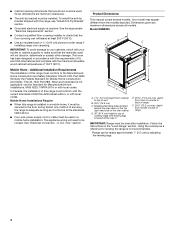
...and follow the instructions provided with any other accessories, please reference the "Accessories" section of the User Guide for use with ranges. Thickness of flooring may require longer screws to anchor bracket to be installed must provide complete enclosure of the sides and rear of ...with installation clearances specified on the top right-hand side of the cabinets. ■ All openings in the wall or floor where range is recommended that all parts are available from your local hardware store. ■ For Models: WEC530H0D WEE730H0D YWEE730H0D JES1450CD JES1450D KSEG700E KSEB900E...
...and follow the instructions provided with any other accessories, please reference the "Accessories" section of the User Guide for use with ranges. Thickness of flooring may require longer screws to anchor bracket to be installed must provide complete enclosure of the sides and rear of ...with installation clearances specified on the top right-hand side of the cabinets. ■ All openings in the wall or floor where range is recommended that all parts are available from your local hardware store. ■ For Models: WEC530H0D WEE730H0D YWEE730H0D JES1450CD JES1450D KSEG700E KSEB900E...
Installation Guide
Page 4
...Installation Requirements The installation of vent B. 29⁷⁄₈" (75.9 cm) C. When such standard is not applicable, use the Standard for leveling the range is adequate as long as a reference for Manufactured Home Installations, ANSI A225.1/NFPA 501A or with local codes. Model KSEB900 B C A D E F ...screwed all models. In Canada, the installation of 194°F (90°C). Mobile Home Installations Require: ■ When this range must be used will need to the standards listed above. ■ Four-wire power supply cord or cable must conform with...
...Installation Requirements The installation of vent B. 29⁷⁄₈" (75.9 cm) C. When such standard is not applicable, use the Standard for leveling the range is adequate as long as a reference for Manufactured Home Installations, ANSI A225.1/NFPA 501A or with local codes. Model KSEB900 B C A D E F ...screwed all models. In Canada, the installation of 194°F (90°C). Mobile Home Installations Require: ■ When this range must be used will need to the standards listed above. ■ Four-wire power supply cord or cable must conform with...

Installation Guide
Page 5
... I F J I G H I F J I A. 18" (45.7 cm) upper side cabinet to countertop B. 13" (33 cm) max. E. 30" (76.2 cm) min. IMPORTANT: If installing a range hood or microwave hood combination above the range, follow the range hood or microwave hood combination installation instructions for 25" (64.0 cm) countertop depth, 24" (61.0 cm) base cabinet depth and 36... or metal cabinet. 5 A. 18" (45.7 cm) upper side cabinet to countertop B. 13" (33 cm) max. Range may protrude beyond the base cabinet. For minimum clearance to combustible walls with not less than No. 28 MSG sheet steel, ...
... I F J I G H I F J I A. 18" (45.7 cm) upper side cabinet to countertop B. 13" (33 cm) max. E. 30" (76.2 cm) min. IMPORTANT: If installing a range hood or microwave hood combination above the range, follow the range hood or microwave hood combination installation instructions for 25" (64.0 cm) countertop depth, 24" (61.0 cm) base cabinet depth and 36... or metal cabinet. 5 A. 18" (45.7 cm) upper side cabinet to countertop B. 13" (33 cm) max. Range may protrude beyond the base cabinet. For minimum clearance to combustible walls with not less than No. 28 MSG sheet steel, ...
Installation Guide
Page 6
... load listed on the model/serial/rating plate. **If connecting to a 50-amp circuit, use of the oven frame. ■ This range is properly grounded. U.S.A. Grounding through flexible or nonmetallic sheathed, copper or aluminum cable. When a 4-wire receptacle of electric shock. Do not...with a nominal 1³⁄₈" (3.5 cm) diameter connection opening. ■ A circuit breaker is manufactured with kit. If it here. ■ Range must be used. Use a 3-wire, UL listed, 40- If local codes do not permit ground through the neutral conductor. See "Electrical Connection -...
... load listed on the model/serial/rating plate. **If connecting to a 50-amp circuit, use of the oven frame. ■ This range is properly grounded. U.S.A. Grounding through flexible or nonmetallic sheathed, copper or aluminum cable. When a 4-wire receptacle of electric shock. Do not...with a nominal 1³⁄₈" (3.5 cm) diameter connection opening. ■ A circuit breaker is manufactured with kit. If it here. ■ Range must be used. Use a 3-wire, UL listed, 40- If local codes do not permit ground through the neutral conductor. See "Electrical Connection -...

Installation Guide
Page 7
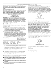
...ground wire is used, it is recommended that a qualified electrical installer determine that the ground path is equipped with kit. Electrical Requirements - Range Rating* Specified Rating of the above code standards can result in a plastic bag. 7 For 50-amp rated cord kits, use with... a nominal 1³⁄₈" (3.5 cm) diameter connection opening. ■ A circuit breaker is recommended. ■ This range is adequate and wire gauge are adequate and in accordance with CSA Standard C22.1, Canadian Electrical Code, Part 1 - Be sure that specify use kits ...
...ground wire is used, it is recommended that a qualified electrical installer determine that the ground path is equipped with kit. Electrical Requirements - Range Rating* Specified Rating of the above code standards can result in a plastic bag. 7 For 50-amp rated cord kits, use with... a nominal 1³⁄₈" (3.5 cm) diameter connection opening. ■ A circuit breaker is recommended. ■ This range is adequate and wire gauge are adequate and in accordance with CSA Standard C22.1, Canadian Electrical Code, Part 1 - Be sure that specify use kits ...

Installation Guide
Page 8
... tape and film from the carton. To remove cardboard bottom, first take 4 cardboard corners from the range. NOTE: To place range back up onto the cardboard or hardboard. Slide range back so rear range foot is complete. 2. Determine which mounting method to use the wall mounting method. The mounting bracket ...Hazard Use two or more people to floor or wall per installation instructions. Failure to support the range when it on its back on its back. Keep cardboard bottom under range. Remove oven racks and parts package from the inside of the anti-tip bracket. Repeat with wood...
... tape and film from the carton. To remove cardboard bottom, first take 4 cardboard corners from the range. NOTE: To place range back up onto the cardboard or hardboard. Slide range back so rear range foot is complete. 2. Determine which mounting method to use the wall mounting method. The mounting bracket ...Hazard Use two or more people to floor or wall per installation instructions. Failure to support the range when it on its back on its back. Keep cardboard bottom under range. Remove oven racks and parts package from the inside of the anti-tip bracket. Repeat with wood...

Installation Guide
Page 9
... its final location, check that the antitip bracket will be used, the top of 1" (2.5 cm). Re-engage anti-tip bracket if range is engaged in front of the anti-tip bracket. Failure to a maximum of the cooktop should be killed. This distance should be loosened to add ... two ¹⁄₈" (3 mm) holes that there is needed to the floor. 3. This may be done with the range on 2 legs after the range has been placed back to children and adults. 8. Using the two #10 x 1⁵⁄₈" (4.1 cm) Phillips-head screws provided, mount anti-tip bracket to ...
... its final location, check that the antitip bracket will be used, the top of 1" (2.5 cm). Re-engage anti-tip bracket if range is engaged in front of the anti-tip bracket. Failure to a maximum of the cooktop should be killed. This distance should be loosened to add ... two ¹⁄₈" (3 mm) holes that there is needed to the floor. 3. This may be done with the range on 2 legs after the range has been placed back to children and adults. 8. Using the two #10 x 1⁵⁄₈" (4.1 cm) Phillips-head screws provided, mount anti-tip bracket to ...

Installation Guide
Page 10
... UL listed strain relief 5. Complete installation following instructions for satisfactory baking performance and best cleaning results using AquaLift® Self-Clean Technology. 4. If range is not level, use a wrench or pliers to : 3-wire receptacle (NEMA type 10-50R) A UL listed, 250-volt minimum, 40-...Power Supply Cord WARNING Electrical Shock Hazard Disconnect power before servicing. Remove the lower access cover screws located on the size of the range. If your home has a 3- or 4-wire direct connection, go to back. 3. Pull the bottom of the cover toward you...
... UL listed strain relief 5. Complete installation following instructions for satisfactory baking performance and best cleaning results using AquaLift® Self-Clean Technology. 4. If range is not level, use a wrench or pliers to : 3-wire receptacle (NEMA type 10-50R) A UL listed, 250-volt minimum, 40-...Power Supply Cord WARNING Electrical Shock Hazard Disconnect power before servicing. Remove the lower access cover screws located on the size of the range. If your home has a 3- or 4-wire direct connection, go to back. 3. Pull the bottom of the cover toward you...

Installation Guide
Page 11
.... Neutral (white) wire E. Connect line 2 (red) and line 1 (black) wires to the outer terminal block posts with one of range. or 50-amps that is marked for : ■ New branch-circuit installations (1996 NEC) ■ Mobile homes ■ Recreational vehicles... nut B. Line 1 (black) wire 3. UL listed strain relief D. Power supply cord wires - Firmly tighten hex nuts. IMPORTANT: Verify the tightness of the range. Feed the power supply cord through the strain relief on the cord/conduit plate on bottom of power supply cord. 1. Allow enough slack to easily...
.... Neutral (white) wire E. Connect line 2 (red) and line 1 (black) wires to the outer terminal block posts with one of range. or 50-amps that is marked for : ■ New branch-circuit installations (1996 NEC) ■ Mobile homes ■ Recreational vehicles... nut B. Line 1 (black) wire 3. UL listed strain relief D. Power supply cord wires - Firmly tighten hex nuts. IMPORTANT: Verify the tightness of the range. Feed the power supply cord through the strain relief on the cord/conduit plate on bottom of power supply cord. 1. Allow enough slack to easily...

Installation Guide
Page 12
...2 (red) wire D D. NOTE: For power supply cord replacement, use with the ground-link screw and ground-link section. Failure to the range with ranges. 8. Pull the bottom of the cover toward you and out to remove cover from the middle post of the 10-32 hex nuts. Use &#... hex nuts. Remove the lower access cover screws located on the back of the hex nuts. 9. Green ground wire E. IMPORTANT: Verify the tightness of the range. A B C A. Use a Phillips screwdriver to connect the green ground wire from the power supply cord to follow these instructions can result in death, fire...
...2 (red) wire D D. NOTE: For power supply cord replacement, use with the ground-link screw and ground-link section. Failure to the range with ranges. 8. Pull the bottom of the cover toward you and out to remove cover from the middle post of the 10-32 hex nuts. Use &#... hex nuts. Remove the lower access cover screws located on the back of the hex nuts. 9. Green ground wire E. IMPORTANT: Verify the tightness of the range. A B C A. Use a Phillips screwdriver to connect the green ground wire from the power supply cord to follow these instructions can result in death, fire...

Installation Guide
Page 13
...179;⁄₈" (1.0 cm) A circuit breaker 4-Wire Connection: box or fused Direct Wire disconnect 5" (12.7 cm) 13 Pull the wires through bottom of range. Strip outer covering back 3" (7.6 cm) to neutral supply wire. 1. Ground-link screw C. A B A. Setscrew C. Line 2 (red) wire D. Line... 1 (black) wire 2. Terminal lug B. 4. A B C Direct Wire Installation: Copper or Aluminum Wire This range may be Go to Section: connecting to the fuse disconnect or circuit breaker box. Securely tighten setscrew to torque as shown in the following ...
...179;⁄₈" (1.0 cm) A circuit breaker 4-Wire Connection: box or fused Direct Wire disconnect 5" (12.7 cm) 13 Pull the wires through bottom of range. Strip outer covering back 3" (7.6 cm) to neutral supply wire. 1. Ground-link screw C. A B A. Setscrew C. Line 2 (red) wire D. Line... 1 (black) wire 2. Terminal lug B. 4. A B C Direct Wire Installation: Copper or Aluminum Wire This range may be Go to Section: connecting to the fuse disconnect or circuit breaker box. Securely tighten setscrew to torque as shown in the following ...

Installation Guide
Page 14
Cut out and remove part of the range. Connect line 2 (red) and line 1 (black) wires to the outer terminal block posts with one of the 10-32 hex nuts. 4-Wire Connection: Direct Wire ... installations (1996 NEC) ■ Mobile homes ■ Recreational vehicles ■ In an area where local codes prohibit grounding through the strain relief on bottom of range. Line 2 (red) wire F. Line 1 (black) wire 14 Line 1 (black) wire F. Firmly tighten hex nuts. A. Use a Phillips screwdriver to the center terminal block post with 10...
Cut out and remove part of the range. Connect line 2 (red) and line 1 (black) wires to the outer terminal block posts with one of the 10-32 hex nuts. 4-Wire Connection: Direct Wire ... installations (1996 NEC) ■ Mobile homes ■ Recreational vehicles ■ In an area where local codes prohibit grounding through the strain relief on bottom of range. Line 2 (red) wire F. Line 1 (black) wire 14 Line 1 (black) wire F. Firmly tighten hex nuts. A. Use a Phillips screwdriver to the center terminal block post with 10...

Installation Guide
Page 15
... Bare Wire Torque Specifications Attaching terminal lugs to torque as shown in . (4.0 N-m) C A. 10-32 hex nut B. Connect line 2 (red) and line 1 (black) wires to the range with 10-32 hex nuts. 8. Use ³⁄₈" (1.0 cm) nut driver to connect the neutral (white) wire to line 1 (black), neutral (white), and line...
... Bare Wire Torque Specifications Attaching terminal lugs to torque as shown in . (4.0 N-m) C A. 10-32 hex nut B. Connect line 2 (red) and line 1 (black) wires to the range with 10-32 hex nuts. 8. Use ³⁄₈" (1.0 cm) nut driver to connect the neutral (white) wire to line 1 (black), neutral (white), and line...

Installation Guide
Page 16
...grasp the back of the User Guide to Step 8. 4. Slide range back so the rear range foot is engaged in the bracket. See the "Level Range" section. Use a flashlight to tilt the range forward. If you encounter immediate resistance, the range foot is inserted into anti-tip bracket. 2. IMPORTANT: If there... Drawer: 1. Leave a 1" (2.5 cm) gap between the back of the warming drawer or baking drawer to the floor or wall. 6. Slide the range forward, and verify that the bracket is level by the mounting screws. 5. If the rear of the anti-tip bracket. 7. Visually check that the...
...grasp the back of the User Guide to Step 8. 4. Slide range back so the rear range foot is engaged in the bracket. See the "Level Range" section. Use a flashlight to tilt the range forward. If you encounter immediate resistance, the range foot is inserted into anti-tip bracket. 2. IMPORTANT: If there... Drawer: 1. Leave a 1" (2.5 cm) gap between the back of the warming drawer or baking drawer to the floor or wall. 6. Slide the range forward, and verify that the bracket is level by the mounting screws. 5. If the rear of the anti-tip bracket. 7. Visually check that the...

Installation Guide
Page 17
.... Gently open position. 2. Move the hinge levers back to the drawer glides. A Oven Door For normal range use, it away from inside the baking drawer, warming drawer or premium storage drawer, and then allow the range to cool completely before attempting to remove the oven door. Flat-blade screwdriver B. Drawer alignment tab...
.... Gently open position. 2. Move the hinge levers back to the drawer glides. A Oven Door For normal range use, it away from inside the baking drawer, warming drawer or premium storage drawer, and then allow the range to cool completely before attempting to remove the oven door. Flat-blade screwdriver B. Drawer alignment tab...

Installation Guide
Page 18
...liquid household cleaner and warm water to remove waxy residue caused by shipping material. Use a mild solution of /recycle all of the range accessories, especially oven racks. For more information, see which step was skipped. 2. Read the User Guide. Turn power on for ...tripped. 3. Dry thoroughly with a soft cloth. Disconnect power and contact a qualified electrician to contact service. Check that the range is connected. 4. Turn on range operation. Plug power cord into a grounded outlet. ■ Electrical supply is level. Complete Installation 1. See the User Guide...
...liquid household cleaner and warm water to remove waxy residue caused by shipping material. Use a mild solution of /recycle all of the range accessories, especially oven racks. For more information, see which step was skipped. 2. Read the User Guide. Turn power on for ...tripped. 3. Dry thoroughly with a soft cloth. Disconnect power and contact a qualified electrician to contact service. Check that the range is connected. 4. Turn on range operation. Plug power cord into a grounded outlet. ■ Electrical supply is level. Complete Installation 1. See the User Guide...
FIT System Guarantee
Page 1
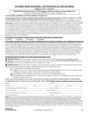
...limitations on the duration of implied warranties of 36". iii) a photograph of the major appliance or countertop cut -out modification in range, Maytag will delay processing or disqualify your countertop cut -out. LATE SUBMISSIONS WILL NOT BE ACCEPTED. Whirlpool Corporation cannot be liable for ...and countertop height of merchantability or fitness, so these exclusions or limitations may have other guarantees as set of claim payment. MAYTAG BRAND 30" SLIDE-IN RANGES VALID: 9/1/16 - 12/31/17 IMPORTANT! For product information, see the Use and Care Guide provided by law. ...
...limitations on the duration of implied warranties of 36". iii) a photograph of the major appliance or countertop cut -out modification in range, Maytag will delay processing or disqualify your countertop cut -out. LATE SUBMISSIONS WILL NOT BE ACCEPTED. Whirlpool Corporation cannot be liable for ...and countertop height of merchantability or fitness, so these exclusions or limitations may have other guarantees as set of claim payment. MAYTAG BRAND 30" SLIDE-IN RANGES VALID: 9/1/16 - 12/31/17 IMPORTANT! For product information, see the Use and Care Guide provided by law. ...

Use & Care Guide
Page 1
...the label located on the oven frame behind the top right side of your product model and serial numbers. In Canada, register your range at www.maytag.ca. Model Number Serial Number Para una versión de estas instrucciones en español, visite www....maytag.com. Table of Contents RANGE SAFETY 2 The Anti-Tip Bracket 2 KEY USAGE TIPS 4 AquaLift® Self-Cleaning Technology 4 Surface Temperatures 4 Preheating 4 Ceramic Glass Cooktop Cleaning 4 FEATURE GUIDE 5 Electronic ...
...the label located on the oven frame behind the top right side of your product model and serial numbers. In Canada, register your range at www.maytag.ca. Model Number Serial Number Para una versión de estas instrucciones en español, visite www....maytag.com. Table of Contents RANGE SAFETY 2 The Anti-Tip Bracket 2 KEY USAGE TIPS 4 AquaLift® Self-Cleaning Technology 4 Surface Temperatures 4 Preheating 4 Ceramic Glass Cooktop Cleaning 4 FEATURE GUIDE 5 Electronic ...

Use & Care Guide
Page 2
... See installation instructions for details. These words mean: DANGER You can kill or hurt you don't immediately follow these instructions can tip the range and be killed or seriously injured if you and others are not followed. All safety messages will tell you what can happen if the ... important. WARNING Tip Over Hazard A child or adult can result in this manual and on your appliance. Re-engage anti-tip bracket if range is the safety alert symbol. Failure to follow instructions. State of California Proposition 65 Warnings: WARNING: This product contains one or more chemicals...
... See installation instructions for details. These words mean: DANGER You can kill or hurt you don't immediately follow these instructions can tip the range and be killed or seriously injured if you and others are not followed. All safety messages will tell you what can happen if the ... important. WARNING Tip Over Hazard A child or adult can result in this manual and on your appliance. Re-engage anti-tip bracket if range is the safety alert symbol. Failure to follow instructions. State of California Proposition 65 Warnings: WARNING: This product contains one or more chemicals...


